The mentioned powerfets from Hitachi was used in 1981-1983 by a danish company in a 100w mosfet amplifier.
Mind telling the brand/model ?
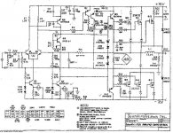
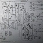
Attached is the Soundcraftsmen schematic. this is the same basic amp used in many models. the PCR-800 is the basic model and includes the PM-860, pro power series etc.
They did have a class-H series and that is a totally different amp.
The PCR and Pro-Power series have an odd regulated power supply called a Phase Controlled Regulator. it works like I light dimmer. The basic amp circuit might sound better with a conventional supply. It does not have the last word on bass extension in stock form and i have always wanted to play with the building a conventional power supply and see how it sounds vs stock.
The Basic Mosfet schematic is straight out of the RCA handbook I am told with the exception of the switch from bipolar to Mosfets. Long tailed pair input with CC source. and dual VAS stages. what I like about this amp is the large driver transistors. the Motorola 2N3440/5416 combo are pretty beefy devices. Now interestingly. they choose NOT to use the 2N5416 match to the 3440 but instead went to the MM4003 why? I find that curious. now what I do know is that the P channel Mosfet has a LOT more gate capacitance vs the N-channel device. and both devices are way way up there anyway vs today's Mosfets.
I have long suspected that a beefy driver stage is needed to properly run these Mosfets without that famed mosfet mist these early devices were always described as. I think too many companies tried to run this with wimpy light weight driver stages and the massive amounts of gate capacitance would just roll off the top end. or color it or...mist it...whatever... Where as the SC amps always had this beefy driver stage.
I have seen/heard other amps that use the MJE-340/350 devices and never liked the sound.
Switching between a PCR and say a Bryston 4b is a drastic difference in sound. the 4B adds an octave to the bottom end but also adds a large degree of harsh grain to the top end. the SC is far more listenable.
Keeping these devices cool is essential as they will pass more current the cooler they are. however. they sound better when they are warm. so there is a bit of a trade off there.
2 pairs will easily make 200+ watts @ 8 ohms with a +/- 70vdc supply. and one pair sounds even better at half the power.
a revamped circuit with a better front end and even beefier driver devices would be very interesting. I have always wanted to build such an animal!
* of note in the schematic, it shows 3 pairs of output devices. however only the "pro" version of the amp had the 3 output pairs. the "home" versions of the amp all used 2 pairs and hence sounded better. also the pro versions changed the feedback resistors and caps. presumably for better stability under hard use.
Attachments
Last edited:
Mitronic
- Was a very small company called Mitronic, made by two or three electronic engineers around 1979-80. They sold the model M100 as ready mono modules or as a finished stereo amplifier. The company is now closed.
Mind telling the brand/model ?
- Was a very small company called Mitronic, made by two or three electronic engineers around 1979-80. They sold the model M100 as ready mono modules or as a finished stereo amplifier. The company is now closed.
Attached is the Soundcraftsmen schematic. this is the same basic amp used in many models. the PCR-800 is the basic model and includes the PM-860, pro power series etc.
They did have a class-H series and that is a totally different amp.
The PCR and Pro-Power series have an odd regulated power supply called a Phase Controlled Regulator. it works like I light dimmer. The basic amp circuit might sound better with a conventional supply. It does not have the last word on bass extension in stock form and i have always wanted to play with the building a conventional power supply and see how it sounds vs stock.
The Basic Mosfet schematic is straight out of the RCA handbook I am told with the exception of the switch from bipolar to Mosfets. Long tailed pair input with CC source. and dual VAS stages. what I like about this amp is the large driver transistors. the Motorola 2N3440/5416 combo are pretty beefy devices. Now interestingly. they choose NOT to use the 2N5416 match to the 3440 but instead went to the MM4003 why? I find that curious. now what I do know is that the P channel Mosfet has a LOT more gate capacitance vs the N-channel device. and both devices are way way up there anyway vs today's Mosfets.
I have long suspected that a beefy driver stage is needed to properly run these Mosfets without that famed mosfet mist these early devices were always described as. I think too many companies tried to run this with wimpy light weight driver stages and the massive amounts of gate capacitance would just roll off the top end. or color it or...mist it...whatever... Where as the SC amps always had this beefy driver stage.
I have seen/heard other amps that use the MJE-340/350 devices and never liked the sound.
Switching between a PCR and say a Bryston 4b is a drastic difference in sound. the 4B adds an octave to the bottom end but also adds a large degree of harsh grain to the top end. the SC is far more listenable.
Keeping these devices cool is essential as they will pass more current the cooler they are. however. they sound better when they are warm. so there is a bit of a trade off there.
2 pairs will easily make 200+ watts @ 8 ohms with a +/- 70vdc supply. and one pair sounds even better at half the power.
a revamped circuit with a better front end and even beefier driver devices would be very interesting. I have always wanted to build such an animal!
* of note in the schematic, it shows 3 pairs of output devices. however only the "pro" version of the amp had the 3 output pairs. the "home" versions of the amp all used 2 pairs and hence sounded better. also the pro versions changed the feedback resistors and caps. presumably for better stability under hard use.
Thanks - I have several valve amplifiers from KT88, 7581A to EL84. The TVA-1 delivers approx. 65-70W - and hot as ....! The sonic sound from my old mosfet amplifier M100 with two pairs in the outputstage ( I don't have the mos amplifier anymore) sounded very good in my ears. A little more clear sound in mid and highrange and I would never have sold it!
My idea is to try and make the input and driverstage from Luxman L58A, the only problem is that you said one pair of the 50/135 mosfets sounds better than two in parallel. The L58A sounds beautiful up to lets say half power, 35w. In my opinion the L58A would have been a killer with a double pair in the outputstage!
I agree with you that the MJE340/350 should be used in other aplications than drivers for fets. The Motorola BF757/60 was made as video devices I think, but they sounds pretty good in the circuit shown. Yes - the output fets need "hardcore" drivers!
Do we know some available input fets like SJ44/SK163 - to92 I think? - found SJ44 to 20$ - much to expensive! - SK163 by Cricklewood, UK to resonable 1-2£ . There have to be other possibilities!!
Do you have any suggestion to the "optimal" circuit??
rgds
90% of the time!
First - the Propower series: Long time ago I was told by the danish company to make a regulated psu for the mosfet inputstage. This should increase sound quality?
The second thing you mention about different capacitance between the P and N mos was the reason why my friend like to use bipolar instead of mosfet transistors.
The Motorola 2N3440 is a TO39, 1A 250V device - and 350V for 2N5416 . Not bad for a driver.
The Motorola BF760/BF757 , 250V 0,5A TO202 house - see attached pdf.
The MJE340/50 TO 126 - lets keep them out.
As far as the heat dissipation is concerned I like the TO220 house - at the time in 1982 I think that the BF760 with TO202 housing was the best solution. It is more difficult with a cooling star on top of TO39? - don't you think?
I am not in a position to say whether the MM4003 is more rugged or more powerful to compensate for the different capacitance of the outputs.
Bottom line: I would like to built a well sounding "animal" as you put it! It is not that easy for me to make the PCB - so - Is it possible to find a circuit which is reliable and at the same time sounds even more detailed and better than the circuit already attached? If I knew that the L58A circuit could work with a double pair of Hitachi's - I would never ask for more!!! But the input fets is the problem!
rgds
Forgot: I know that 90% of the time you use less than 1-2W power - but for the last 10% of listening time its' nice to have enough ! -)) smile.
The PCR and Pro-Power series have an odd regulated power supply called a Phase Controlled Regulator. it works like I light dimmer. The basic amp circuit might sound better with a conventional supply. It does not have the last word on bass extension in stock form and i have always wanted to play with the building a conventional power supply and see how it sounds vs stock.
Long tailed pair input with CC source. and dual VAS stages. what I like about this amp is the large driver transistors. the Motorola 2N3440/5416 combo are pretty beefy devices. Now interestingly. they choose NOT to use the 2N5416 match to the 3440 but instead went to the MM4003 why? I find that curious. now what I do know is that the P channel Mosfet has a LOT more gate capacitance vs the N-channel device. and both devices are way way up there anyway vs today's Mosfets.
I have seen/heard other amps that use the MJE-340/350 devices and never liked the sound.
Switching between a PCR and say a Bryston 4b is a drastic difference in sound. the 4B adds an octave to the bottom end but also adds a large degree of harsh grain to the top end. the SC is far more listenable.
2 pairs will easily make 200+ watts @ 8 ohms with a +/- 70vdc supply. and one pair sounds even better at half the power.
a revamped circuit with a better front end and even beefier driver devices would be very interesting. I have always wanted to build such an animal!
First - the Propower series: Long time ago I was told by the danish company to make a regulated psu for the mosfet inputstage. This should increase sound quality?
The second thing you mention about different capacitance between the P and N mos was the reason why my friend like to use bipolar instead of mosfet transistors.
The Motorola 2N3440 is a TO39, 1A 250V device - and 350V for 2N5416 . Not bad for a driver.
The Motorola BF760/BF757 , 250V 0,5A TO202 house - see attached pdf.
The MJE340/50 TO 126 - lets keep them out.
As far as the heat dissipation is concerned I like the TO220 house - at the time in 1982 I think that the BF760 with TO202 housing was the best solution. It is more difficult with a cooling star on top of TO39? - don't you think?
I am not in a position to say whether the MM4003 is more rugged or more powerful to compensate for the different capacitance of the outputs.
Bottom line: I would like to built a well sounding "animal" as you put it! It is not that easy for me to make the PCB - so - Is it possible to find a circuit which is reliable and at the same time sounds even more detailed and better than the circuit already attached? If I knew that the L58A circuit could work with a double pair of Hitachi's - I would never ask for more!!! But the input fets is the problem!
rgds
Forgot: I know that 90% of the time you use less than 1-2W power - but for the last 10% of listening time its' nice to have enough ! -)) smile.
Attachments
Last edited:
Hi,
I also build 4 or 5 amps with 2sj50/2sk135. The oldest must be almost 20 years old by now and it´s still working.
I also experimented with bias. Big improvement up to 200mA, after that still getting better but more subtle.
I also used them without source resistors but found it a bit difficult to check the bias per device so now I´m using 5x1watt resistors per fet.
Here´s a picture of my current amp
william
Could upload your circuit diagram of your Amp?
Mitronic PA100 2SJ50/2SK135 build and first test.
With some delay because of repair of several Luxman amplifiers a.m., the Mitronic PA100 is ready for the complete measuring test.
The first data from the Mitronic PA100 at only +-30Vdc and 50mA pr. output device:
https://picasaweb.google.com/vbkolsen/MitronicPA100#5873396040978440882
MITRONIC PA100 and the first measurement data:
The plus / minus 30 Vdc and 50 mA for each output transistor revealed the following data:
At 100kHz / 1 Watt output power was the PA100 amplifier - 0.1 dB down.
At 250kHz / 1 Watt output power was the PA100 amplifier - 1.0 dB down.
There could not be measured higher in frequency as the built-in RC circuits 10R / 47N in the amplifier limited the measurement.
By only + - 30Vdc and an output power of 1 Watt, and from 20 Hz to 20 kHz on the HP distortion analyzer, the overall distortion was below 0.02%.
Quite good of the design from 1982.
At full voltage of about +-60Vdc will the amplifier undoubtedly provide other measurement data.
https://picasaweb.google.com/vbkolsen/MitronicPA100#5873397038376433890
MITRONIC PA100.
All transistors measured after Hfe, amplification:
Right channel: 2SA970 BL Hfe: 296, 296, 295
BF760 Hfe: 116
BF757 Hfe: 120/120
Hitachi 2SJ50: 1,151V, 1,141V.
Hitachi 2SK135: 0.943V , 0,939V.
Right channel DC offset: <0.507 mV DC
The incredibly low DC offset is a result of the measured transistors.
https://picasaweb.google.com/vbkolsen/MitronicPA100#5873397619801908146
MITRONIC PA100.
All transistors measured after Hfe, amplification:
Left channel: 2SA970 BL Hfe: 301, 302, 299
BF760 Hfe: 117
BF757 Hfe: 121/116
Hitachi 2SJ50: 1,341 V, 1,340 V
Hitachi 2SK135: 1,044 V, 1,040 V
Left channel DC offset: <4,502 mV DC
The incredibly low DC offset is a result of the measured transistors. The left channel DC offset however, is approx. 4mV higher than the Right channel, but still very low.
Overall view of the Mitronic PA100:
https://picasaweb.google.com/vbkolsen/MitronicPA100#
This MITRONIC PA100 amplifier circuit seems to work nicely. It is difficult to spot any shortcomings in the first measurement tests , I would say") ......but more to come.....
......but more to come.....
http://www.tubeamp.hobbysider.dk
Mind telling the brand/model ?
With some delay because of repair of several Luxman amplifiers a.m., the Mitronic PA100 is ready for the complete measuring test.
The first data from the Mitronic PA100 at only +-30Vdc and 50mA pr. output device:
https://picasaweb.google.com/vbkolsen/MitronicPA100#5873396040978440882
MITRONIC PA100 and the first measurement data:
The plus / minus 30 Vdc and 50 mA for each output transistor revealed the following data:
At 100kHz / 1 Watt output power was the PA100 amplifier - 0.1 dB down.
At 250kHz / 1 Watt output power was the PA100 amplifier - 1.0 dB down.
There could not be measured higher in frequency as the built-in RC circuits 10R / 47N in the amplifier limited the measurement.
By only + - 30Vdc and an output power of 1 Watt, and from 20 Hz to 20 kHz on the HP distortion analyzer, the overall distortion was below 0.02%.
Quite good of the design from 1982.
At full voltage of about +-60Vdc will the amplifier undoubtedly provide other measurement data.
https://picasaweb.google.com/vbkolsen/MitronicPA100#5873397038376433890
MITRONIC PA100.
All transistors measured after Hfe, amplification:
Right channel: 2SA970 BL Hfe: 296, 296, 295
BF760 Hfe: 116
BF757 Hfe: 120/120
Hitachi 2SJ50: 1,151V, 1,141V.
Hitachi 2SK135: 0.943V , 0,939V.
Right channel DC offset: <0.507 mV DC
The incredibly low DC offset is a result of the measured transistors.
https://picasaweb.google.com/vbkolsen/MitronicPA100#5873397619801908146
MITRONIC PA100.
All transistors measured after Hfe, amplification:
Left channel: 2SA970 BL Hfe: 301, 302, 299
BF760 Hfe: 117
BF757 Hfe: 121/116
Hitachi 2SJ50: 1,341 V, 1,340 V
Hitachi 2SK135: 1,044 V, 1,040 V
Left channel DC offset: <4,502 mV DC
The incredibly low DC offset is a result of the measured transistors. The left channel DC offset however, is approx. 4mV higher than the Right channel, but still very low.
Overall view of the Mitronic PA100:
https://picasaweb.google.com/vbkolsen/MitronicPA100#
This MITRONIC PA100 amplifier circuit seems to work nicely. It is difficult to spot any shortcomings in the first measurement tests , I would say
......but more to come.....http://www.tubeamp.hobbysider.dk
- Status
- This old topic is closed. If you want to reopen this topic, contact a moderator using the "Report Post" button.
- Home
- Design & Build
- Parts
- 2sk135 2sj50