
djk said:While that's true (and I have used the EB60 boards too), the question you just responded to was asked over six years ago.
It's not easy being old...six years ago I probably would'nt have made such a blunder.. sorry to take up your time.
I have found this schematics from a site of flowchart software !!!
Novagraph Chartist 5.0 - Mosfet Amplifier Diagram
E.T.I. Audio Project P.104
what E.T.I. is it ?
I was just flicking through my old eti magazines and found this. It's project 499 general purpose mosfet amp on p.104/105, from ETI Audio Projects Dec 1982.
Attachments
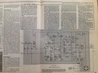
That sch is wrong.
The top side outputs are drawn upside down. The bottom side uses Nchannel symbols.
I wonder how many other mistakes are in there?
The bias voltage of 0.8Vbias could be correct. But it's more likely to be ~1.5Vbias to turn on the two gates.
The mosFETs really need an EF stage after the VAS/TIS.
RV1 is a terrible way to adjust output offset. Don't do that !
Compare the front end to any of the SymaSym variants on this Forum.
Last edited:
Well spotted, I've looked at that schematic loads of times and not even noticed the mosfets are drawn incorrectly! Anyway when I was fiddling with these mosfets in the 1980s and 90s I used the voltage drop of a diode for each mosfet. So in the above diagram the bias voltage would be about 1.1v resulting in about 70ma per mosfet. This amp was intended by eti as a PA amp so the bias was kept low to keep it cool. But the crossover distortion on mosfet circuits like this is worse than the equivalent bipolar emitter follower which is why the negative feedback is so high in an attempt to correct it. Modern double pole compensation techniques would lessen HF distortion even further. But run at low voltage and in class A this amp's THD would be vanishingly low. Further things I fiddled with were to short out C3 altogether and thermally couple both input transistors.
0.8V bias is inadequate.
My Soundcraftsmen with 2sj50 and 2sk135 (2 pairs) uses 0.8 v bias (factory setting). Why do you say this is too low. At 0.8 v you get 200mA bias current.
http://www.embedded.com/print/4015850
Check out this page, it's Douglas Self's explanation of crossover distortion in different output stage topologies.
Check out this page, it's Douglas Self's explanation of crossover distortion in different output stage topologies.
Another one for the Hitachi devices....
You may well not know, but the famed Roksan ROK-S1 power amp used EXACTLY this circuit configuration with higher voltage supplies: +/-58V (and higher voltage rating semis of course), and the successors of the 2SK134-2SJ58 (the 2SK1058-2SJ162), and a rally beefy power supply.
The sound of that amp was fabulous.
First simple mosfet amplifier circuit by K134+J49
in the meantime this types also obsolete2SK134 and 2SJ49
Dear member
If you need to change mosfet 2SK134 and 2SJ49 do not use 10N16 or 10P16 use this mosfet Below and you may need to change heatsink because this mosfet are TO3P.
For 2SK134 Replace with 2SK1058
For 2SJ49 Replace with 2SJ162
https://www.mouser.de/ProductDetail/Renesas-Electronics/2SK1058-E?qs=ZVKuL1Ob8AtV9PPbawzCEg==
have EXICON good replacements available ?
http://www.exicon.info/products.php
https://www.profusionplc.com/de/type/lateral-mosfet
I'm surprised that no one has mentioned, or may know about, the Lazarus Electronics H1(A) power amps. These were apparently designed by Allen Wright and built in the early '90's by Greg Miller of Glendale CA. They are an integrated design using (in each channel) a 6922 in the front end coupled to J77/K214's driving 3 pairs of J49/K134's. Could be biased for AB or class A putting out around 50 watts. I heard these many years ago and have had a pair of them working pretty-much-daily duty for 20 years. Sound ABSOLUTELY MARVELOUS. Lazarus also made a higher power monoblock design (which didn't sound nearly as good) and a preamplifier (tubed I believe).
Reviewe in IAR magazine in the early 90's - and highly rated.
Charles
Reviewe in IAR magazine in the early 90's - and highly rated.
Charles
Hey everyone,
Reviving this thread because after some considerable searching I have not had a lot of luck fining a 25 watt (give or take) Class A amp using these mosfets.
I have several original pairs of the Hitachi k134/J49 (12 of each). I've had them since the late 80's and they are known to be originals and in good operational order. I am looking for a schematic for a Class A amp as I noted above using these mosfets or a design that is easily convertible to using these mosfets. Any help you folks can offer would be greatly appreciated. I have been mostly a tube OTL guy for the last 30 years and recently built a Hiraga Le Monstre 8w amp and love it except its just a bit to shy on watts. Thx in advance!
Most models of Conrad Johnson are tube amps, but any few models use the mentioned MOSFET's in the output stage in Class-A mode
https://www.usaudiomart.com/details...-amplifier-with-owners-manual/images/2296818/
https://www.diyaudio.com/archive/gallery/showphoto.php/photo/8203/size/big.1.html
https://www.diyaudio.com/community/threads/class-a-of-a-conrad-johnson-evo2000.329684/
https://www.diyaudio.com/community/threads/clone-conrad-johnson-evolution-2000.322441/
https://www.diyaudio.com/community/...-motif-new-for-me-are-there-any-infos.244543/
Attachments
Last edited:
Thx so much and I greatly appreciate this but I am not seeking a hybrid design. I am looking for a full solid state design. Also when I go online to seek out the specs for the CJ amp and look at the schematic it appears to be biased in its first few watts Class A then its a straight AB class amp at 200 watts. I was seeking a full on Class A amp design with 25ish watts that could use the noted Hitachi devices and I have done a good bit of searching and have not found any.
Long time ago (2/1986) in the Audio Amateur was published the Lang 20W Class-A Mosfet Power Amplifier:
https://tempo333.blogspot.com/2015/05/the-class-mosfet-ology.html?view=sidebar
https://www.diyaudio.com/community/...class-a-amplifier-boards-2sk134-2sj49.409398/
https://de.scribd.com/document/389179055/The-Lang-20W-Class-A-Mosfet-Amplifier
https://www.analog-forum.de/wbboard...ennt-jemand-den-lang-20-w-class-a-mosfet-amp/
There s a mistake in the Lang amplifier when it comes to supplying the cascoded VAS voltage limiter, the base of the transistor
is fed through a 18V zener, so that will set the voltage at 6V in respect of each supply rail but those 6V will sag once the amp is loaded since the supply voltage will be lower under load.
That could work but it s not this way that it should be implemented, also the base is tied to the rail with a 10k resistance that is too high AC wise, not counting that there s no current limitation through the zener, a quite hasardous design overall, actually the 18V zener should be replaced by a 10k resistance and the 10k that goes from base to the voltage rail should be replaced by a 3.9- 4.7 zener.
- Home
- Amplifiers
- Solid State
- 2SJ49/2SK134