2SA1455K/ 2SC3722K SMD has Ft: 140mHz, Hfe: "R" 180~390
2SA970/2SC2240 has Ft: 100mHz, Hfe: "GR" 200~400
If one looks at linearity and current, it seems that the old 970/2240 has better specs as far as linearity is concerned.
Need one pair for amplifier input.
Any advice would be highly appreciated.
Gudmund
2SA1455K pdf, 2SA1455K description, 2SA1455K datasheets, 2SA1455K view ::: ALLDATASHEET :::
2SA970 pdf, 2SA970 description, 2SA970 datasheets, 2SA970 view ::: ALLDATASHEET :::
Last edited:
Point is that I have at least 100 pairs of 970/2240....but the recommended 1455/3722 SMD for the circuit seems to have a linearity not quite as good as the 970/2240?
search an answer on this one.....?
I don't know where you get the less good linearity from. Cob for the Rohm parts even seems to be a bit lower (~3.4 pF vs. 4.0 pF at -10 V for the PNPs), which correlates with the somewhat higher fT. Feel free to derive Early voltages from Ie(Vce) for yourself, but those appear to be similar.
The devices to beat remain Sanyo's 2SA1016/2SC2362 (Cob = 2.2 pF for the PNP), but unfortunately those have been discontinued for a while.
The devices to beat remain Sanyo's 2SA1016/2SC2362 (Cob = 2.2 pF for the PNP), but unfortunately those have been discontinued for a while.
2SA970/2SC2240 are very good as input devices, otherwise you can add the 2SA872A/2SC1775A to the list of such good devices provided by the members above.
Thank you for the answer...the question was: why did the circuit designer change to the 1455/3722 SMD devices? ...did the SMD transistors perform better than the Toshiba 970/2240 devices he used earlier, or did he change the input transistors because of the obsolete 970/2240 Toshiba transistors? I have tried to measure Hfe by some of the 1455/3722 devices, and they have just about the same gain difference as the 970/2240...I do not have equipment to measure the noise...
.... unfortunately the 2SA872 is not available by my local supplier.
I shall test the circuit with the 970/2240 transistors.
Gudmund
The devices to beat remain Sanyo's 2SA1016/2SC2362 (Cob = 2.2 pF for the PNP), but unfortunately those have been discontinued for a while.
I tried to look for the Sanyo 2SA1016/2SC2362 but they were sold out as well.
I am sure you are right about the linearity of the 1455/3722, and that they are fine replacements for the 970/2240....but SMD's are difficult to handle, and I have problems with home-made double-sided PCB's ....the hope is to keep the noise level in line with the SMD devices.
Gudmund
Last edited:
Don't sweat this issue over the ultimate performance of parts. There are very few through-hole types to choose from now without the high risks and costs of sourcing doubtful NOS parts.
Designers change parts specifications for very practical reasons, not as many imagine, to get the absolute optimum part quality. The real decisions are about a few principal electrical specs, physical format, price, availability, lead time, obsolescence etc.
So use the 2SC2240/A970 types you have with confidence - or the ideal replacements commonly specified here on the forum i.e. KSC1845/A992
Last edited:
So use the 2SC2240/A970 types you have with confidence -
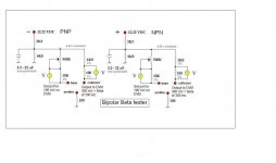
Can I have your opinion on the attached setup test? A simple test to determine beta on small signal transistors.
Attachments
It seems to be a well planned design for small signal transistors, as an adaptor to a DVM but it needs a reversible and regulated or very stable 12VDC power source. Does your DMM not have a transistor test socket which will do this well enough?
Include a socket that will adapt to all likely bipolar transistors since some will have different pinouts. ZIF sockets are often used for this but they are a chore to configure and mark for multiple parts and pin spacings. To find what pinouts are, just googling "2SC2240 pinout" for example, works fine with a little practice to get the search engine aligned to your context. As a final suggestion, don't handle the transistors while testing as even the slight heat of fingers will cause the readings to change significantly.
Include a socket that will adapt to all likely bipolar transistors since some will have different pinouts. ZIF sockets are often used for this but they are a chore to configure and mark for multiple parts and pin spacings. To find what pinouts are, just googling "2SC2240 pinout" for example, works fine with a little practice to get the search engine aligned to your context. As a final suggestion, don't handle the transistors while testing as even the slight heat of fingers will cause the readings to change significantly.
It seems to be a well planned design for small signal transistors, as an adaptor to a DVM but it needs a reversible and regulated or very stable 12VDC power source. Does your DMM not have a transistor test socket which will do this well enough?
Include a socket that will adapt to all likely bipolar transistors since some will have different pinouts. ZIF sockets are often used for this but they are a chore to configure and mark for multiple parts and pin spacings. To find what pinouts are, just googling "2SC2240 pinout" for example, works fine with a little practice to get the search engine aligned to your context. As a final suggestion, don't handle the transistors while testing as even the slight heat of fingers will cause the readings to change significantly.
Thanks for your reply.
I do have a very stable +-24Vdc / 1A adjustable powersupply and the thought was a 1/2 8 dil socket for the different pinouts. I have checked some transistors with my DVM, but the 9V battery don't last very long time and the readings varies. I think a stable psu works better. And yes..the heat from fingers change the readings.
I don't know where you get the less good linearity from. Cob for the Rohm parts even seems to be a bit lower (~3.4 pF vs. 4.0 pF at -10 V for the PNPs), which correlates with the somewhat higher fT. Feel free to derive Early voltages from Ie(Vce) for yourself, but those appear to be similar.
The devices to beat remain Sanyo's 2SA1016/2SC2362 (Cob = 2.2 pF for the PNP), but unfortunately those have been discontinued for a while.
I could not answer you because of the connection between pF and voltage, which I did not quite understood at the time you wrote it. Someone explained it to me .
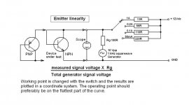
As for test of output transistor and emitter linearity, I have received a circuit from a friend of mine: https://sites.google.com/site/httpstubeamp/
Find the link and circuit somewhere on the middle of the site at Picasaweb.
Emitter linearity seems to be important because as the emitter current rises the internal transistor resistance drops. In a symmetrical circuit it is important that all transistors in both halfperiods has the same type and number.
As I understood the explanation: by higher current the emitter-working-point is or should be on the flat part of the linearitycurve, and that most of the usual intermodulation which occurs in the outputstage can be avoided...and that the intermodulation gets worse by heavy load or difficult speakerload.
That should be the reason why we have to measure emitter linearity on the output transistors.
Am I wrong on this one?
Attachments
Last edited:
(~3.4 pF vs. 4.0 pF at -10 V for the PNPs), which correlates with the somewhat higher fT.
The devices to beat remain Sanyo's 2SA1016/2SC2362 (Cob = 2.2 pF for the PNP), but unfortunately those have been discontinued for a while.
My friend uses 970/2240 as diff. input and
Sanyo 2SA1370/2SC3467 , 200V, 1W, Ft: 150mHz, 1,7pF, Hfe: "D" = 60~120 ..for current and predriver,
2SB1186a/2SD1763a 120V, 20W, Ft: 80mHz, 20pF, Hfe: "E" = 100~200...as drivers.
The four test OP's: Sanken 2SA1294/2SC3263 , 230V, 15A, Ft: 60mHz , 250pF, Hfe: 50
The test setup circuit made by hardwiring is going on.
The capacitor will show ~ 8.2Vdc and this is a good value to use.Can I have your opinion on the attached setup test? A simple test to determine beta on small signal transistors.
Gugmund's arrangement tests the device at a very low Vce. The advantage of Gudmund's is that Pq is much lower and thus temperature change is much lower as well as slower. But Vcb is zero and that is not representative of in circuit voltages.
You don't need Re. It can be set to 0r0 and the tester still works.
The big advantage to using 500k VR is that you can check hFE at a variety of Ic
Last edited:
The capacitor will show ~ 8.2Vdc and this is a good value to use.
Gugmund's arrangement tests the device at a very low Vce. The advantage of Gudmund's is that Pq is much lower and thus temperature change is much lower as well as slower. But Vcb is zero and that is not representative of in circuit voltages.
You don't need Re. It can be set to 0r0 and the tester still works.
The big advantage to using 500k VR is that you can check hFE at a variety of Ic
Thanks for your reply. Ok, in the test setup I will try without Re.
It is my friend who works with the amplifier circuit, and I do not know the resistor values and idle current for the 970/2240 at the actual voltage.
The current might stay around 1,5 ~3mA for each of the two diff. input transistors.
My idea was to keep the test transistors in the circuit for approx. 30 sek., and then check hFe....in order to get close transistor match how many different Ic check points would you suggest for each transistor?
To match transistors I and others recommend you adopt an LTP style jig.
I also recommend that you thermally couple the two transistors and that your jig be capable of checking that both pass the same current and have the same Vce. To match Pq and thus match Tj.
I tried to find some info about the "Long tailed pair style jig" setup circuit. Do you have a link for the LTP jig? Otherwise I have to search for some information about the subject.
Yes, I have erlier tried with thermally coupled transistors when testing hFe, but not current and Vce at the same time.
Cordell posted a jig.
If you have a pair of matched collector load resistors, 1k0 0.1%, and the two bases are connected, then when the two BJTs are matched you will find that the 1k0 Vdrops are identical and the two collector voltages are identical and since the bases are connected these ensure that Vcb and Vbe are also identical. All those give identical Vce and identical Ic. Thus identical Pq and Tj.
But the jig is very intolerant of small errors in the device pair.
You will see big differences in 1k0 Vdrop. Use one device as REF and measure all the others against it.
Batch all the devices for their Vdrops.
You will get many that have similar Vdrop.
Now select a new REF' from a close reading batch and test all the others against the REF'. Now when you get a very close match you can sweep the Ib over a range either side of your expected operating current. If Vdrop stays close to REF', then you have a matched pair. Label them and never sell them, they are special !.
Select a new REF" and start again.
Cordell posted a jig.
If you have a pair of matched collector load resistors, 1k0 0.1%, and the two bases are connected, then when the two BJTs are matched you will find that the 1k0 Vdrops are identical and the two collector voltages are identical and since the bases are connected these ensure that Vcb and Vbe are also identical. All those give identical Vce and identical Ic. Thus identical Pq and Tj.
But the jig is very intolerant of small errors in the device pair.
You will see big differences in 1k0 Vdrop. Use one device as REF and measure all the others against it.
Batch all the devices for their Vdrops.
You will get many that have similar Vdrop.
Now select a new REF' from a close reading batch and test all the others against the REF'. Now when you get a very close match you can sweep the Ib over a range either side of your expected operating current. If Vdrop stays close to REF', then you have a matched pair. Label them and never sell them, they are special !.
Select a new REF" and start again.
Thank you...Your selection method looks logical to me. This way of close match and transistor selection will take some time, but I think the work is worth all the trouble, if the goal is a DC stable symmetrical amplifier without global feedback and servo.
Can I have your opinion on the attached setup test? A simple test to determine beta on small signal transistors.
The test circuit I posted to Gudmund, was a copy from a french site, but the 12VDC-voltage mentioned seems to be inadequate to reach reliable readings.
If the DC voltage is raised to 16VDC, and the first DMV is adjusted to 100mV measured accross the 10K = 10uA , the readings gets better.
In the setup the adjustment pot is 470K, and the 47K5 is added in order to keep the 100mV/10K within the measuring range of the pot.
The 970/2240 1370/3467 1145/2705 sounds good between 2 to 3mA
The mentioned transistors shall be used in a modified DC-amplifier without global feedback. The DC-amplifier is on test. The wire hook-up amplifier passes 300kHz without visible dB loss on the oscilloscope, and complete stable even with long cables between pre drivers and lapt Sanken outputs.
KJH
https://sites.google.com/site/httpstubeamp/
- Status
- This old topic is closed. If you want to reopen this topic, contact a moderator using the "Report Post" button.
- Home
- Amplifiers
- Solid State
- 2SA1455K/2SC3722K SMD vs 2SA970/2SC2240