Thanks to the wonderfull info in this thread I was able to repair an old amp from the early 80s.
I saved it from the junk yard. Powered it up last night. Sounds briliant.
BTW BEL india is still making the 2N3055 and it is readily available in India. Its also made using the old process.
I have a few doubts about some mismatched transistors in the amp i.e. BC147B has been replaced with BC547b should this bother me ?
Trans used.
2N3055HV x 4
2n3019 NPN x 4
2N4033 PNP x 2
BC5547B PNP x 1
BC147B NPN (Sot25) x 1
https://bel-india.in/Products.aspx?MId=14&LId=1&link=87
Hi chinoy,
I have found that transistors produced by other factories do not behave like the originals. Close enough I guess. I would normally never use a 2N3055 in audio. It's a power supply pass transistor - designed that way.
The signal transistor sub should be fine. Make sure the pinout is correct.
I have found that transistors produced by other factories do not behave like the originals. Close enough I guess. I would normally never use a 2N3055 in audio. It's a power supply pass transistor - designed that way.
The signal transistor sub should be fine. Make sure the pinout is correct.
The problem with MJ21195/6 or MJ15003/4 on old boards is that the Ft is >2 mhz, whereas homotaxial 2n3055 had about 200 khz. Depending on chinoy's 1980's product, these newer transistors may cause oscillation.
bel-india did not allow me to view the datasheet referenced for 2n3055hv, bouncing me to a home page where I can view the security link pages. If bel 2n3055hv has the low Ft of homotaxial parts, then the oscillation problem is solved. OTOH reviewers in 1966 announced that a product built out of select (for higher Iceo voltage) RCA 2n3055 (40636 probably) had bad sounding highs, compared to vacuum tube amps of the same production date. Upgrade of that amp to 2 mhz parts like TIP3055 sounded much better on content with high frequencies, owners report. I never owned any working homotaxial 2n3055 so my experience is with copies of MJ15003 (NTE60). Highs were great with 50 mhz (2n5320/22) and 30 mhz drivers (MJE15028/29), dull with 6 mhz drivers (TIP31c/32c).
bel-india did not allow me to view the datasheet referenced for 2n3055hv, bouncing me to a home page where I can view the security link pages. If bel 2n3055hv has the low Ft of homotaxial parts, then the oscillation problem is solved. OTOH reviewers in 1966 announced that a product built out of select (for higher Iceo voltage) RCA 2n3055 (40636 probably) had bad sounding highs, compared to vacuum tube amps of the same production date. Upgrade of that amp to 2 mhz parts like TIP3055 sounded much better on content with high frequencies, owners report. I never owned any working homotaxial 2n3055 so my experience is with copies of MJ15003 (NTE60). Highs were great with 50 mhz (2n5320/22) and 30 mhz drivers (MJE15028/29), dull with 6 mhz drivers (TIP31c/32c).
Last edited:
Ha! Would you look at that... I built this amp a very long time ago (more than 5 decades... lol) when I was in Year 6... I also designed a little PCB... used a texta marker, HCL and H2O2... The original output transistors were Motorola 2N3055, which I replaced with Motorola 2N3773 with major sound improvement.
These days I use MPSA18, BD139/140, MJE15030/15031 and MJ15024/15025.... mostly because 20 years ago I bought large quantities...

These days I use MPSA18, BD139/140, MJE15030/15031 and MJ15024/15025.... mostly because 20 years ago I bought large quantities...

If the outputs are configured as followers and dominant pole compensation is used, installing faster outputs almost never causes global loop oscillations. in fact slower transistors can cause oscillation due to the non-dominant poles coming down in frequency eating into the phase margin. If an oscillation does develop it’s usually local to the output stage, and curable by adding (or increasing) base stoppers.
2N3773’s have a hell of a lot better current gain linearity than 3055’s. And the MJ15003 grew out of the 2N3773 die family - at least Motorola’s version of it.
2N3773’s have a hell of a lot better current gain linearity than 3055’s. And the MJ15003 grew out of the 2N3773 die family - at least Motorola’s version of it.
https://static1.squarespace.com/sta...63e1d89f5277f56705/1655092581521/2N3055HV.PDF
'NOTE: This device is also available in Defence/ Miltary, HIREL, JANXXX Grades'.
CDIL, same item.....https://www.cdil.com/metal-can-transistors/2n3055hv-1
Searched, and found same device from CDIL, it is a 100 V version instead of the lower voltage on the regular device, you can check for frequency performance. Note is on their web page.
BEL is mainly defense oriented, the stock sold in the civil market may be excess production or inspection rejects from the parts intended for defense use.
BEL supplies can be erratic, they focus on defense production, see their site.
It does meet minimum specifications, another issue is fakes (!)....stick to CDIL, last they were 40 Rupees when I asked.
Fake BEL are about 20 Rupees.
Last edited:
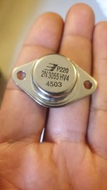
Here is a pic of the Transistor I picked up a few as I plan to keep this amp for a long time.Hi chinoy,
I have found that transistors produced by other factories do not behave like the originals. Close enough I guess. I would normally never use a 2N3055 in audio. It's a power supply pass transistor - designed that way.
The signal transistor sub should be fine. Make sure the pinout is correct.
Got started in audio when I decided to try and re-create my dads / our families first amp an akai amp AM-2400 purchased in 1979. First I restored a STK akai amp. Was not happy with it. Then I built a few chip amps based on the TDA and LM chip amps. Was not impressed. Then picked up a few transistor amps based on the Toshiba 2sa1943 / 2sc5200 not impressed.
Then I saw this amp rusted, covered in dirt. One channel not working. Half the caps blown. At a junk yard. The guy hooked it up to small speaker to prove one side was working. And I fell in love with the sound.
I brought it home and the first thing I found was that they had changed the transformer from its orignal 18-0-18 to 18-0-30 as all the caps were 35v it took out quite a few caps.
It looks like a cave man soldered all the wires with a screw driver put in a fire.
What I love about this amp is that unlike all the other amps I have repaired / built / bought the sine wave signal remains sharp and clean from input to output.
This amp has me convinced that the lower the Collector Capacitance (Cc): <=5pf. The lower the Ft. The lower the gain the better it sounds. Or the less chance of oscillations.
All the amps I own even the Akai STk which is 40 watts RMS I can play at max volume. But this puppy I cant even push to 80%. The akai is on 42 volts d/c rails this one is on 26 d/c rails. And I think I can pump up the voltage a lot more esp as I have replaced all the electro caps with brand new 63v ones.
I still have to figure out a way to bias the amp. As there is zero documents or schematics I need to be sure before I finger it.
Esp as its working so well.
My OCD will not allow me to mix the BC147 and BC547. So I will put in a matched pair there for sure.
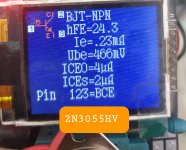
Here is a pic of the BEL transistor and I have a screen shot of its value from a component tester.
These are HV units so are technically supposed to handle high voltages than the regular old plain jane 3055.
The good news is the original 3055HV transistors from that era are still on the amp and still working fine.
These are picked up as backups as they are dirt cheap.
My Plan is to build another copy of this amp for my engine simulator. Its job will be to mimic a source coil inside a motor cycle that puts out a voltage off 100V peak to peak at different RPMS. i.e. 1 to 300 hz.
I tested every transistor I own on the tester and have created a database of the values I got.
Noticed that batch to batch Hfe is stable. But same transistor different make or even batch and the hfe values change. So the thought of these dis-similar transistors triggers my ocd.
Here is the pic of the transistor. Let me see if I can add the value screen also. I did not solder a wire to the case so if the values look off let me know and I will re-run it with a soldered wire to the case.
Right now I have a toroidal 18-0-18 powering it. I may up this to a 24-0-24 toro latter. Though I have heard people driving these to 50-60 volt rails with no problem. The heat sink on this is weak. So the guy who sold it to me for 5$ said stick to the original transformer values. And Im more than happy with it like this. I have started collecting Transformers and Heat sinks off high end audio equipment from the junk yards. As I think they are 100 times better than the china made crap or the locally made crap.
Ps: BEL makes these for our defence sector. So they have to be MIL spec and no messing around. You can find pics with the cap removed and you see the insides look better than the units made by On Semi and other companies.
Ps2: They also make the 2N3773. But its costlier. May use the 3773 on the engine simulator.
Attachments
Last edited:
There are a lot of youtube videos of this integrated amplifier but unfortunately no exist images especially concerning the internal stuff - online-pictures from InageShack in the meantime all deleted - go to
https://www.hifivision.com/threads/give-away-woodstock-amp-sa-4000-speakers-optimus-120-mk-ii.34055/
https://www.hifivision.com/threads/give-away-woodstock-amp-sa-4000-speakers-optimus-120-mk-ii.34055/
That's correct, but nevertheless there are hard to beat vintage amps with 2N3055 with all its disadvantages in terms of parasitic effects compared to last generation BjTs (LAPT, MET etc.).Those are better transistors in every way imaginable.
These days I use MJ21195 and MJ21196, or the MJL variant. Better beta holdup with current. That and they match much, much closer!
This means, a very good transistor doesn't make a very good amplifier.
The main reason for starting this thread was the desire to get an overview of all amplifiers that managed to achieve a good end result in a listening test thanks to good development despite pronounced deficiencies within the power transistors used at the time.
P.S.: Anywhere on thos or other forum I had read a listening test between 2N3055 and MJ21196 (or MJ15003) so as modern SANKEN LAPT BjT's (on Rod Elliott's DoZ). Who know the URL therefore ?
Last edited:
I have tons of pictures and videos I took while preparing this amp. Let me upload to google drive and share the link.There are a lot of youtube videos of this integrated amplifier but unfortunately no exist images especially concerning the internal stuff - online-pictures from InageShack in the meantime all deleted - go to
https://www.hifivision.com/threads/give-away-woodstock-amp-sa-4000-speakers-optimus-120-mk-ii.34055/
Even though I have it working. What I really want is to find a schematic that matches it. So I can understand it better.
Some basic tracing of signals and wires I had to do anyway. But its far from being a fully blown schematic.
The problem with these old amps is its spaghetti of wires and you touch anything the wire comes off. And wires are just randomly soldered to tracks. Im amazed how good it sounds in spite of all these short comings.
Its made up of 4 main boards.
1. PSU Board.
Nothing special here. Except for the snubber resistors and the fact that they are only 4 1000Uf caps for the amp and one 1000uf dedicated to the preamp and Phono board.
2. Tone control board.
Just two transistors BC149c and some caps. Only has treble and bass. I want to boost the bass some so I need to understand this schematic.
3. Phono section:
This is where the input signal enters the picture. It has 8 Transistors and a few caps.
4. Main Amp board.
This has the 4 3055s and some driver transistors 2N4033 / 2N3019 / BC147B / BC557B
Two transistors have been replaced here with unmarked cans but as its a stero I can figure out what they have replaced. The BC147B has been replaced with a BC547B and the Unmarked can is a 2N3019
Will start organising and uploading the pics in a bit. I never took them to be shared just for my own reference so its a mess.
Since it plays and sounds good. My last step is to just figure out how to set the two trim pots which I suspect is for Bias setting.
The Phono section looks interesting and takes up half the case space. Its very tight for space. So I could not even update the 1000uf PSU caps cause that is the only size that fits. Id like to keep it as original as possible.
All electro caps have been replaced. The 2 watt 4 ohm wire wound resistors are cracked but still work. Last step will be to clean up the cover repaint it and replace the stupid Philips 2 pin output pins with something more modern and regular looking cause I cant find those 2 pin male speaker connectors in my country.
The schematisch in #306 ist a Siemens design, first published in the German FUNKSCHAU magazine in 1971, mainly to promote their own BD130 transistors, a 2N3055 equivalent. Subsequently many German vendors offered complete kits with PCB's to hobbyists. I've built almost a dozen of them. They were quite robust and reliable, even in guitar and Bass amps that I've built. But you needed to chose the VAS transistor according to the rail voltages, of course. The BC547b as suggested by Siemens didn't always serve well.
Didn't I show build instructions incl. PCB layout earlier in this thread?
Best regards!
Didn't I show build instructions incl. PCB layout earlier in this thread?
Best regards!
Afaik the 2N3442 fT is just some tens of kHz. I have a box full of them, but refused to use them for audio purpuses due to this.The first higher voltage 'version' of 2N3055 was 2N3442 > right up to 140V vce, BUT only 10A .
Cascading them allowed for much higher power amplifiers than using the 3055's.
Best regards!
First step to increasing power of a class AB power amp is to check the datasheets for Vce and Iceo. More than twice the unloaded rail voltage, good. Also rail cap rating, >120% of rail voltage.Right now I have a toroidal 18-0-18 powering it. I may up this to a 24-0-24 toro latter. Though I have heard people driving these to 50-60 volt rails with no problem. The heat sink on this is weak. So the guy who sold it to me for 5$ said stick to the original transformer values. And Im more than happy with it like this. I have started collecting Transformers and Heat sinks off high end audio equipment from the junk yards.
Second step is calculate or increase the heat sink. Heat sinks cost money, and bargain amps usually leave a lot of it out. Only brands known for 24/7 beach bar reliability buy enough heat sink and/or fan. Fortunately, I've found good sources of used heat sinks in VFD motor drives, and flat screen TV's. Don't forget the insulator and if mica, heat sink compound. I heat sink my drivers, too, as dynakit did before me.
After heat has been managed, you can up transformer rail voltages. To 80% of capacitor ratings. Original 2n3055 +-18 rails, 2n3055 select for Iceo (40636) +-35 rail, 2n3773 & later etc +-50 rails.
It works like a 2N3055. Depends who make it. Minimum spec is 40 kHz, but no maximum. If it’s a Motorola, or any of the second sources who copy the old Motorola, it will be about 1 MHz. Any of the hometaxial variety could be anywhere between 40 and 800 kHz.Afaik the 2N3442 fT is just some tens of kHz. I have a box full of them, but refused to use them for audio purpuses due to this.
Best regards!
One of my buddies back in the day used Mot 3442’s to rebuild his CS800 and it ran fine - under DJ use. If the SOA was poor, they would have blown. If the fT were really down in the kHz he would have never gotten it to stop oscillating.
The 10 amp rating was due to the early attempts at getting breakdown voltage up. Higher Bvceo meant lower beta (and 3055 was bad enough) and higher vce(sat). At 15 amps, it would often exceed the 117W dissipation rating even turned on as hard as it would go.
Here is one more popular Quasi Amp you can buy today. Im posting the direct link cause there are too many pictures / schematics and info to copy paste. What I like about this design is that he has the transistors on the heat sink.
Something that is missing in many quasi comp amps.
I plant to keep this amp stock. Which is let it remain on 18-0-18. Or max take it up to 24-0-24. The Power caps are already stressed at 35v and there is just no space to put in larger caps.
https://vaspelectronics.com/150w-hifi-qc-amplifier
Something that is missing in many quasi comp amps.
I plant to keep this amp stock. Which is let it remain on 18-0-18. Or max take it up to 24-0-24. The Power caps are already stressed at 35v and there is just no space to put in larger caps.
https://vaspelectronics.com/150w-hifi-qc-amplifier
- Home
- Amplifiers
- Solid State
- 2N3055 inside - commercial famous amplifier models, quasi complementary power output