Not hard if you switch inputs, get noise pickup from storms, etc.
It only takes a very short peak to cause breakdown and zot the entire output section.
You're absolutely right. Destruction of all output devices is instantaneous.
My encounter is not from the inputs. It was the voltage spike on the supply rails. Finally traced the spike to the power amp switch. Big transformer + big filter caps + cheap power switch = big contact spark in switch. That's where I discovered welded contacts and the importance of switch quality and how to use snubbers.
Nothing like blowing things up to learn.
ALthough they are rated at 100V Vcbo they only need a small current to change from "Vcbo" to "Vceo" - and bang.
Right. I think that safely taking serious advantage of the Vcbo means you need to be absolutely certain there is no forward bias much past crossover.
Like guaranteed class B.
In a Class AB amp, the output transistors conduct in only half cycle. Zero to +rails for the top half and Zero to -rails for the bottom transistors.
Only in Class A are the output transistors subjected to rail to rail voltages.
we are concerned with Vceo, a Vceo of around 70volts does not stand a chance with rails totaling 110volts, it doesn't take genius to figure this one out...
I found I had three Motorola "UNIBASE" 2N3055s from 72 and 73, four Motorola 8026, and two 2N3055 CNL 3B all in TO-3 cases. I didn't test anyMJE3055s in TO-220 cases.
I used an HP6448B with the current limit set to 200ma.
All of the transistors made it past 105V except one 72 UNIBASE that broke down at 82V.
Several of the 8026 transistors made it to 120V and one made it to 140V.
I used an HP6448B with the current limit set to 200ma.
All of the transistors made it past 105V except one 72 UNIBASE that broke down at 82V.
Several of the 8026 transistors made it to 120V and one made it to 140V.
we are concerned with Vceo, a Vceo of around 70volts does not stand a chance with rails totaling 110volts, it doesn't take genius to figure this one out...
Well then, please explain why this Maplin amp works. According to you, this amp will blow up at maximum voltage swing. By the way, Vceo is not "around 70V". It is 60V (Absolute Maximum Ratings).
Attachments
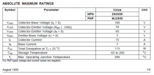
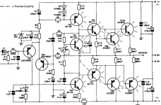
Well then, please explain why this Maplin amp works. According to you, this amp will blow up at maximum voltage swing. By the way, Vceo is not "around 70V". It is 60V (Absolute Maximum Ratings).
we do not know how many amps of those where made and how many blew.....anyway, it is not a good design practice to violate transistor ratings.....they may work, but the question is for how long?
i can not recommend such practice to anyone...
In a Class AB amp, the output transistors conduct in only half cycle. Zero to +rails for the top half and Zero to -rails for the bottom transistors.
you are looking at half of the picture.....
supposing the bottom trannie is conducting to almost the neg rail and the top transistor is cut-off, the off trannies collector emitter junction is still seeing the total rails owing to their physical connection.....there is no avoiding this....
THere are always a spread within a batch and among batches......they may work, but the question is for how long?
i can not recommend such practice to anyone...
But worst case are those ones that takes like 65 Volt before they breakdown.
While other 2N3055 can take more than 100 Volt.
The sound idea is to design for the worst case.
And to take no chances.
Several diagrams here claiming more than 60 Volt and even 110 Volt VCE
are not trustful designs. As a worst case will breakdown 2N3055 transistors.
I see the spirit of electronics is high once again the trumpetor's on let use better semiconductors are at it again. I have enough in my junkbox that's next to new that these amps will cost me all of maybe $5 to $10 dollars why wouldn't i do it. If i want to be build a high quality amp and purchase top line gear i have no problem in achieving that. Clearly if your a so called hobbiest using a transistor that was used in the sixties or seventies make's second grade. Interesting way of puting it. I actually prefer Valve or mosfets amps if i was going to spend my money. But this had nothing to do with that. It's not rocket science why not use the older gear up and put it together and it can be used in applications where one does not give a rats about it. But that must be just a second grade hobbyest opinion
does anyone know or used a good quasi design to utilize those far from ultimate second grade 2n3055 transistor's i'd love to hear from you. I was thinking of using the design that a guy on here i think with the username quasi actually designed his own quasi style amps. Nice amps actually but he did one with bjt's that uses the 2n3773 style transistor i couldn't see why you couldn't use the same design with 2n3055 but just lower the voltage rails. Nbip300 - Quasi's DIY Audio Site I must seriously say i personally think that they are really nice amplifiers on that site very nice
does anyone know or used a good quasi design to utilize those far from ultimate second grade 2n3055 transistor's i'd love to hear from you. I was thinking of using the design that a guy on here i think with the username quasi actually designed his own quasi style amps. Nice amps actually but he did one with bjt's that uses the 2n3773 style transistor i couldn't see why you couldn't use the same design with 2n3055 but just lower the voltage rails. Nbip300 - Quasi's DIY Audio Site I must seriously say i personally think that they are really nice amplifiers on that site very nice
as long as you scale down the power supply rails to +/-35volts, you can use "quasie's" design using those 2n3055's
you can use the bd139,bd140 drivers instead.
Semiconductor devices like most things follow distribution curves. A manufacturer has two choices. (1) sell all the parts at the lowest common denominator to optimize sales (early transistor choice like the 2N3055), or (2) grade the parts and charge a premium for the higher voltage units (more modern approach as in the VP0106).
Even with approach 2, there is a high probability that the demand for the high grade parts will fall below the availibility from the distribuition curve, so parts are only screened for the high grade parameter untill sales requirements are meet. Then the next lower screening occurs, and so forth. The latter parts end up having a significant percentage of high grade (voltage in this case) parts marked and sold at the lower cost.
In the case of the 2N3055, I suspect the process was targetted at 100V to get 60V parts. It makes screening easier, and you get a much better yield.
If Y'all want to use 3055s at higher supply voltages, just screen them first. It's easy.
Get a socket (or use clip leads) and place a 100 or 200 ohm resistor in series with the collector. Connect a variable supply + to the resistor and - to the emitter with no connection to the base. Increase the voltage until athe collector to emitter voltage suddenly drops (avalanche). Kill the supply so as not to overheat the transisitor (THEY GET HOT!). Mark the transistor with a felt tip pen, repete for all parts present and sort by breakdown voltage.
Don't forget to give yourself a little margin to account for mains voltage variations.
Those amps worked because the builders got lucky. The distribution of parts was in their favor and the transistors THEY used did not break down.
Best wishes.
Those amps worked because the builders got lucky.
The
of the day !!
OS

check out this thread:does anyone know or used a good quasi design to utilize those far from ultimate second grade 2n3055 transistor's i'd love to hear from you. I was thinking of using the design that a guy on here i think with the username quasi actually designed his own quasi style amps. Nice amps actually but he did one with bjt's that uses the 2n3773 style transistor i couldn't see why you couldn't use the same design with 2n3055 but just lower the voltage rails. Nbip300 - Quasi's DIY Audio Site I must seriously say i personally think that they are really nice amplifiers on that site very nice
http://www.diyaudio.com/forums/solid-state/189599-my-little-cheap-circlophone-2.html#post2585389
Try this http://www.diyaudio.com/forums/solid-state/112935-r-cambridge-a60-help.html
Very highly regarded over here in UK and quasi complementary. The TIP3055 is of course a plastic version of the 2N3055.
Very highly regarded over here in UK and quasi complementary. The TIP3055 is of course a plastic version of the 2N3055.
anyway, it is not a good design practice to violate transistor ratings.....they may work, but the question is for how long?
Yes, but are we looking at the right parameters.
you are looking at half of the picture.....
supposing the bottom trannie is conducting to almost the neg rail and the top transistor is cut-off, the off trannies collector emitter junction is still seeing the total rails owing to their physical connection.....there is no avoiding this....
Yes, the transistor is still subjected to rail voltages even when off.
So, should we not be looking at the maximum voltage a transistor in the Off State can sustain before it goes zap instead of using Vceo as the limit?
Originally posted by TheGimp
Get a socket (or use clip leads) and place a 100 or 200 ohm resistor in series with the collector. Connect a variable supply + to the resistor and - to the emitter with no connection to the base. Increase the voltage until athe collector to emitter voltage suddenly drops (avalanche). Kill the supply so as not to overheat the transisitor (THEY GET HOT!). Mark the transistor with a felt tip pen, repete for all parts present and sort by breakdown voltage.
Yes, but are we looking at the right parameters.
Yes, the transistor is still subjected to rail voltages even when off.
So, should we not be looking at the maximum voltage a transistor in the Off State can sustain before it goes zap instead of using Vceo as the limit?
Vceo Voltage collector to emitter base open or at no current!
i built a leach superamp using these 2N3055/MJ2955 output trannies, i scaled down the rails to +/-55volts unloaded....
that was in 1990, afaik, the amp still lives today.....
i still hold that transistor specs should be respected.....
That does not violate transistor ratings. The original Ampzilla transistors were 80 volt devices. Nice, complementary high gain high current devices, but 80 volt rated (and not much I-s/b to speak of).
If Y'all want to use 3055s at higher supply voltages, just screen them first. It's easy.
Get a socket (or use clip leads) and place a 100 or 200 ohm resistor in series with the collector. Connect a variable supply + to the resistor and - to the emitter with no connection to the base. Increase the voltage until athe collector to emitter voltage suddenly drops (avalanche). Kill the supply so as not to overheat the transisitor (THEY GET HOT!). Mark the transistor with a felt tip pen, repete for all parts present and sort by breakdown voltage.
No. Use a low current source (1 to 5 mA) with a 400 volt compliance. This will keep power dissipation tolerable, even in avalanche. And you do want enough voltage to actually see where it is. THEN heat the device up with a soldering iron, and note the apparent change in Vceo. The leakage will increase at high temps.
- Status
- This old topic is closed. If you want to reopen this topic, contact a moderator using the "Report Post" button.
- Home
- Amplifiers
- Solid State
- 2n3055 amp claims 200 to 220 watt