Thanks guys.
I guess I will skip the AZ1's for right now. Ebay they are running around $89 ea. I have the 80's so I guess I will stick with them for now.
Mogliaa
I am going to purchase 2) boards with the IXYS fets on them. Going to use two VR tubes to lower the B+ before the CCS plate load. I guess I could burn up the extra B+ with dropping resistors but I guess I like the looks of VR's.
Is not critical to regulate precisely the CCS input voltage, what is important is to eliminate ripple as much as you can whilst providing a lower supply output resistance. The shunt regulator is great for this. I have an CLCLC stage followed by a Salas regulator and is dead quiet.
What are you planning to use as your HT filtering stage?
Cheers,
Ale
What are you planning to use as your HT filtering stage?
Cheers,
Ale
Hi,
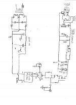
One of my prior posts have attached files of the power supply and line stage chassis.
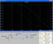
an LC stage will be quite poor filtering for this preamp. it will provide around 9dB attenuation at 100Hz. See attached quick simulation in LTspice
What is the maximum capacitor recommended for the 80 rectifier?
I would suggest C1 being an 8-10uF oil motor cap and then moving the 40uF after the choke at least.
cheers,
Ale
Attachments
FWIW, I have been able to measure 120Hz ripple getting through a single depletion FET CCS as you have drawn as the series element in your gas shunt regulator. Somewhere around -110 dB on the output of the preamp (really low, admittedly).
Replacing with a cascode CCS eliminated it completely. Note that when using the mu output of your active load, power supply rejection is lost, so any eensey weensey ripple will be present on your output. Up to you if that little bit matters.
Replacing with a cascode CCS eliminated it completely. Note that when using the mu output of your active load, power supply rejection is lost, so any eensey weensey ripple will be present on your output. Up to you if that little bit matters.
zigzagflux
What are your suggestions? Since I would like to make this the best that I can on a shoe string budget I'm very open to what ever you would like to suggest.
When money permits I will upgrade my cheap power supply transformer and filament supply transformer with something better.
Note that when using the mu output of your active load, power supply rejection is lost, so any eensey weensey ripple will be present on your output. Up to you if that little bit matters.
Not quite sure what you mean here. Is there a better way to use the cascode IXYS fets?
Did the 15000uF mean to appear at the output of the CCS? I think that may be bad for startup SOA of the CCS FET. Also, the VR tubes won't like to see more than about 40nF of capacitance, so it should be decoupled from the VRs. I think the 15000u can actually be omitted.
The LV Filament circuit is perfect except for the second choke - it's not needed and many destabilise the regulator.
.
The LV Filament circuit is perfect except for the second choke - it's not needed and many destabilise the regulator.
.
How about this?
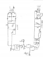
The 1500mfd cap has been removed from the HV supply and replaced with 20mfd/450vdc
The second choke was actually a sloppily drawn resistor. I removed it also
Picture number 3 has the above changes.
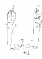
Picture #4 has the VR tubes and assorted junk removed.
Which is the better way to go?
The 1500mfd cap has been removed from the HV supply and replaced with 20mfd/450vdc
The second choke was actually a sloppily drawn resistor. I removed it also
Picture number 3 has the above changes.
Picture #4 has the VR tubes and assorted junk removed.
Which is the better way to go?
Attachments
Last edited:

Please keep asking. I am sure that there are others who will benefit from seeing your design take shape.
For my part, I am happy to review schematics. Being able to say "increase C1" or "delete the choke" does not take much time, and helps to air the design questions that everyone works on. I think we all learn when circuits are talked over, and design choices have to be justified or thrown out.
So keep coming, especially with photos, simulations, schematics. They are all worth a thousand words.
Ok, I will keep asking questions.
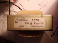
My original thoughts for my power supplies ( one for each channel) were to use the mega filament transformer and the large power supply B+ transformer and a Hammond 157G choke. Plus the fets and VR tubes.
Now the large B+ transformer is way overkill with over 600mA capability as is the filament transformer.
Would I be better off to use a Triad Number 76109 rated at 7.7A @ 6.3 volts for my filament transformer and to use a Chicago PSC-70 rated at 335-0-335 @ MA for my B+ transformer?
Naturally the Hammond choke stays in the mix as do the VR tubes and such.
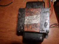
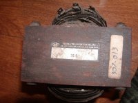
Pictures number 003,004, and 005 are the large transformers and the choke that I originally dug out. Very overkill.
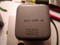
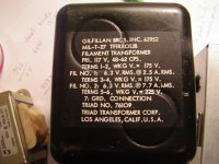
Pictures 001 and 002 are the transformers that I just found and was thinking about using.
Which should I use? Recommendations?
My original thoughts for my power supplies ( one for each channel) were to use the mega filament transformer and the large power supply B+ transformer and a Hammond 157G choke. Plus the fets and VR tubes.
Now the large B+ transformer is way overkill with over 600mA capability as is the filament transformer.
Would I be better off to use a Triad Number 76109 rated at 7.7A @ 6.3 volts for my filament transformer and to use a Chicago PSC-70 rated at 335-0-335 @ MA for my B+ transformer?
Naturally the Hammond choke stays in the mix as do the VR tubes and such.
Pictures number 003,004, and 005 are the large transformers and the choke that I originally dug out. Very overkill.
Pictures 001 and 002 are the transformers that I just found and was thinking about using.
Which should I use? Recommendations?
Attachments
For my part, I enjoy working with over-rated trafos, but maybe the chassis will wind up being very large.
If you would like 250V dc raw supply before the VR tubes, then my best recommendation would be to start with about 330V rms secondary with 150VA rating, and then use choke-input configured supply. With a valve-rectifier and choke input filter, you will get 260 to 280V dc raw output - and you can fine-tune this by using Duncan PSUD2 software.
I use industrial isolation transformers for this task, because the cost is low.
In the UK this means JMS:
150 VA
There should be equivalent firms in your location that can provide these low cost solutions, which work really well. They are best in enclosed housings, since they are not great to look at.
Choke-input filtering means that the rectifier is conducting for a longer part of the 60Hz mains waveform, which is helpful to reduce the peak current. Big current peaks are bad news, because they have wide bandwidth and can easily couple electromagnetically into the signal parts of the circuit. 10H and 50mA handling should be fine if you run 10mA in the VR tubes and up to 10mA in the 26s.
The filament transformer looks too good to miss out on, especially if you want to use Filament bias - the voltage is just about right, and over-rating is doubly good, because the operation is at full-load, the whole time.
- Home
- Amplifiers
- Tubes / Valves
- #26 pre amp