Nothing surprises me with caps. I just spent a while auditioning bypass caps for a 46 driver stage for a 300b SET. In the end no cap was best - this preserved the harmonics and life in the instruments. A really good 47uF polypropylene (big ICW SA) was a bit flat sounding. A cooking ICW poly was a bit more flat sounding and an electrolytic sucked all the life out of the music - quite horrible. With the caps it all sounded very tidy - possibly even a bit less intermodulation distortion in the treble - but by God it was boring to listen to. What's the point of DHTs if you kill the sound with cathode bypass caps. A shame I can't use filament bias easily on a 46. Next best is battery grid bias or a really good unbypassed cathode resistor. Now, 0.1uF Russian teflon FT-3 I can live with easily, but that's about it for caps. In the PSU all polypropylenes.
andy
andy
Hello Pedro,
I'm not fussy about 26s. These are old tubes and condition will be more important than the make. I have a slight preference for globes so I prefer to use those, but the ST ones are nearly as good. I mostly just pull them out of my drawer and plug them in!!
andy
I'm not fussy about 26s. These are old tubes and condition will be more important than the make. I have a slight preference for globes so I prefer to use those, but the ST ones are nearly as good. I mostly just pull them out of my drawer and plug them in!!
andy
What's the point of DHTs if you kill the sound with cathode bypass caps.
andy
This is where I am with DHT's (headamp/preamp), I find the biggest virtue to SET sound is with a good shunt reg big caps are kept out of the loop and the sound great. The nice thing about the 4P1L is higher gain and the filament bias without a cap along with good output impedance, a #26-pre with 4P1l-300B might be a good alternative to the #46 ?
Dear Albert,
The next try is to experiment the effect with different HT filtering cap. You would be surprised for the difference it makes.
Brother Johnny
Brother,
Will try different caps when available.
Thanks for the stand-off strips. It works perfect.
Albert
Nothing surprises me with caps.
<snip!>
A shame I can't use filament bias easily on a 46.
andy
Andy, you can do a variation on filament bias for DHT 46, if you are really interested to try it.
1. Heat the filament with a proper regulator in the usual way
2. Take a second filament regulator, configured for 330mA, connected to a 38V supply.
3. Use an unbypassed 100-ohm cathode resistor.
4. feed the 330mA into the resistor, as if it were the filament current. This generates your -33V bias. Using a high quality current-driven regulator avoids degrading the quality of the 46 stage.
the 100-ohm resistor dissipates 10W, as per the DHT-26 case.
5. The unbypassed Rk 100-ohm decreases the effective gm from 2.35mA/V to 1.9mA/V, - far better than the 0.52mA/V from using an unbypassed 1500-ohm resistor.
6. Enjoy cap-free sound.
.
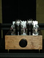
EF184s, again without bypass - the best 300B driver of all).
I don't know exactly why but this made me think of Spinal Tap - "It's in D minor - the saddest key of all".....
Maybe your CLASH logo......!
Andy
Zobal on 1660
George & Salas,
I put the zobal on, 100n with 20k trimmer. The square wave looks pretty good up to about 5k with the trimmer at 4.64k. I make up a 100n & 4.7k, same number as George. Will report after a serious listening.
Rod,
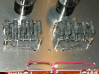
I have the filament resistors re-done with some single stand-off strips which were given by my best friend Johnny. I left a little more room for air circulation. I'll check the temperature and will post the picture later.
Albert
George & Salas,
I put the zobal on, 100n with 20k trimmer. The square wave looks pretty good up to about 5k with the trimmer at 4.64k. I make up a 100n & 4.7k, same number as George. Will report after a serious listening.
Rod,
I have the filament resistors re-done with some single stand-off strips which were given by my best friend Johnny. I left a little more room for air circulation. I'll check the temperature and will post the picture later.
Albert
Rod,
With this set up, the temperature is top at below 100c on couple in a group. I'll leave it to run for sometime and see if there is any other way I could make it better. The voltage after 3 hours are 11.14/9.71v and 11.15/9.74v.
Do I have to tune them back to 11.5v/10v respectively for better operation ??
Albert
Attachments
hi Albert, 100 deg C. sounds reasonable to me.
Is the "Ground" side of the resistors connected to chassis just there? If so, make sure it's the only position. Actually, you can drain a lot of heat into the chassis, using a strip of EMC-type (sticky backed) copper foil between chassis and the resistors, soldered at a few points.
11.15/9.74V is fine for running, just check the bias is where you expect in terms of anode-current. You can fine-tune to, say, 11.2V when hot, if you prefer.
I don't know exactly why but this made me think of Spinal Tap - "It's in D minor - the saddest key of all".....
Maybe your CLASH logo......!
Andy
Not to mention that this design will help you "get all the way to 11" again, without using caps.....
Rod,
Is the "Ground" side of the resistors connected to chassis just there? If so, make sure it's the only position.
It's grounded to the star through the brown wire.
Actually, you can drain a lot of heat into the chassis, using a strip of EMC-type (sticky backed) copper foil between chassis and the resistors, soldered at a few points.
I don't have the foil, but will ask and see if my friend has it by chance.
11.15/9.74V is fine for running, just check the bias is where you expect in terms of anode-current. You can fine-tune to, say, 11.2V when hot, if you prefer.
I thought I'd let it breaking in for sometime then to adjust it. It's time to enjoy. Will report.
Thanks
Albert
Talking of bias, I just had a look at a 26 preamp I built with filament bias and two Hammond 156C anode chokes in series - pretty much the circuit I published earlier on this thread. I was using slightly starved filament - 1.35v and 950mA. bias resistor was 10 ohms as usual with 9.5v on it, so total voltage to be supplied was 9.5 plus 1.35 = 10.85v. Supply to my Coleman board is 15.8v from a 18v secondary, 100uF, Hammond 158ZC choke 2A, 60mH, 10,000uF cap.
With this setup I'm getting 178v on the top of the 156Cs and 148v on the anode. However, this is passing just 4.5mA per tube with the 9.5v bias. Not at all what the curves say!! The chokes have a resistance of 7K.
andy
With this setup I'm getting 178v on the top of the 156Cs and 148v on the anode. However, this is passing just 4.5mA per tube with the 9.5v bias. Not at all what the curves say!! The chokes have a resistance of 7K.
andy
Andy, filament starvation increases anode resistance and curves and to be graphical the anode curves are displaced to the right.
Im traveling at the moment but will try to plot the 26 curves with filament starvation on my return.
Have done it for VT67 recently
Cheers,
Ale
Im traveling at the moment but will try to plot the 26 curves with filament starvation on my return.
Have done it for VT67 recently
Cheers,
Ale
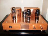
have tried some rectifier tubes that I have on hand, 5R4, 5Y3, 5AR4, CV378, 83 and 5U4G RCA. Love the sound that 5U4G present, more balance.
I have the RCA Cunningham on, will try Reytheon, Syvenia and see if I can hear the different.
Thanks guys for the guidance.
I have the RCA Cunningham on, will try Reytheon, Syvenia and see if I can hear the different.
Thanks guys for the guidance.
Attachments
5R4GY RCA I liked in my 6V6 line pre with least liking 5R4WGB Raytheon. Maybe you got one 5R4GY to test also? Very nice with still more midbass but retaining enough of 5R4GY's open sonic was 5AR4/GZ34. Here pictured with an RCA 5U4G which gave a rather more closed in result than 5R4GY but with richer midbass.
Attachments
- Home
- Amplifiers
- Tubes / Valves
- #26 pre amp