Thanks amandare and Tony!
Yes, 200 V at about 25 ma x 2 (channels) sounds about right. Looking at the Triad choke, at 10 ohms and 50 ma current, that's just a 0.5 V drop. Not much. Am I missing something?
The Hammond 370CAX and its family appear to have very high secondary voltages. Would the 363AX work at 200 V? Even with that one, it looks like the gyrator CCS will be dropping a lot of voltage.
ra7, do not get scared of the higher voltages, it is easy to lose volts, get high H chokes with higher dc resistances....the extra voltage can be taken cared of series resistors...
do not be surprised that a high unloaded voltage easily drop like stones when all tubes have warmed up...
Hammond 370CAX, seems a bit high implied 350 vdc unloaded, but i will use it...
it is better to have more than have much less when you needed it..
do not be surprised that a high unloaded voltage easily drop like stones when all tubes have warmed up...
Hammond 370CAX, seems a bit high implied 350 vdc unloaded, but i will use it...
it is better to have more than have much less when you needed it..
Last edited:
In my post, I mentioned "...out to shunt regulator". Input to regulator is 198 Vdc, CCS current is 20mA (for the regulator) plus 2 x 5mA for the plate of the 26 tubes, so 30mA.
I run my 26 with the H+ exactly what I posted. Pic below. The 5H choke is at the other side of the chassis. Rectifier is AZ1.
I run my 26 with the H+ exactly what I posted. Pic below. The 5H choke is at the other side of the chassis. Rectifier is AZ1.
An externally hosted image should be here but it was not working when we last tested it.
Last edited:
Thanks amandare and Tony!
Yes, 200 V at about 25 ma x 2 (channels) sounds about right. Looking at the Triad choke, at 10 ohms and 50 ma current, that's just a 0.5 V drop. Not much. Am I missing something?
The Hammond 370CAX and its family appear to have very high secondary voltages. Would the 363AX work at 200 V? Even with that one, it looks like the gyrator CCS will be dropping a lot of voltage.
Hello Rahul - The 10H Choke (with C1) is a "Choke-Input Filter". This does more than just drop voltage according to Ohm's Law - it uses magnetic energy storage to smooth-out the peaks of the ac waveform to a lower DC voltage, and reduce the peak currents at the same time. (Web search "Choke-Input Filter" to see all the waveforms, if you have not studied it before).
So long as you can find a suitable choke, it's a very good solution - and if you use the good example posted by Amandrae, you can work with a tried & tested power supply. And since it has been built and measured, please use it, with confidence.
Here's another one I use for Type 01A preamp and basically the same and still using Hammond 370CAX. I am getting 202Vdc from this one feeding a shunt regulator.
You can also see the Rod Coleman CRC supply for the filament regulator of the 01A tubes.

Looking at the bottom left, moving towards the right.....15H choke.....>47UF....>8H choke....>47uF.....>320mH choke (labeled EIA-17 etc.)....>50uF (oil cap).....>shunt reg
You can also see the Rod Coleman CRC supply for the filament regulator of the 01A tubes.
Looking at the bottom left, moving towards the right.....15H choke.....>47UF....>8H choke....>47uF.....>320mH choke (labeled EIA-17 etc.)....>50uF (oil cap).....>shunt reg
Thanks all! Those pics and your description are really helpful amandarae! What is the benefit of using multiple chokes over a single choke? I imagine that the ripple is reduced. My thinking is that a simple CLC filter with the gyrator would provide good PSRR.
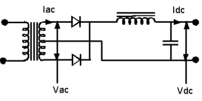
I did look at different filter topologies: RECTIFIER TRANSFORMER CALCULATION
I was looking at the second image, which is a capacitor input full wave rectifier to size the secondary.
Couple more questions:
1. Are there any real sonic benefits to using motor run/oil caps?
2. Amandarae, both images you posted have the PS in its own enclosure. Is the noise and hum really so high that you have to separate the signal circuitry into its own box? I would prefer to keep it in one box.
Thanks all! Those pics and your description are really helpful amandarae! What is the benefit of using multiple chokes over a single choke? I imagine that the ripple is reduced. My thinking is that a simple CLC filter with the gyrator would provide good PSRR.
Possibly, but I have no experience in using a bridge and CLC in my builds. With regards to multiple chokes, simulate your power supply using PSUD and you will see the effect of the chokes with ripple.
I did look at different filter topologies: RECTIFIER TRANSFORMER CALCULATION
I was looking at the second image, which is a capacitor input full wave rectifier to size the secondary.
Couple more questions:
1. Are there any real sonic benefits to using motor run/oil caps? Not in my experienced. I have it at the time, so I use it,
2. Amandarae, both images you posted have the PS in its own enclosure. Is the noise and hum really so high that you have to separate the signal circuitry into its own box? I would prefer to keep it in one box.
My approach was just precautionary when I decided to build the preamps. I figure, the more space I have in the main preamp chassis, the easier to achieved a good layout without wires crossing from each other, or components so close together. I do not enjoy troubleshooting hum due to magnetic coupling. For sure you can build the preamp having everything in one chassis. Please bear in mind that type 26 and 01A tubes are notoriously microphonic (but I am sure you can source for a quiet pair) and sensitive to coupling and vibrations. I am glad that my preamps are quiet ( I have 98 dB speakers)
Last edited:
Thanks about the PSUD2 tip. Teach a man to fish...
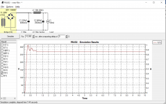
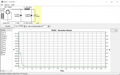
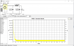
Here is a simple CLC supply. I have spent exactly 30 mins on PSUD2. I need to find out how to calculate the noise value based on ripple voltage. Also, this beer is hitting me hard")
Here is a simple CLC supply. I have spent exactly 30 mins on PSUD2. I need to find out how to calculate the noise value based on ripple voltage. Also, this beer is hitting me hard
Attachments
Couple more questions:
1. Are there any real sonic benefits to using motor run/oil caps?
2. Amandarae, both images you posted have the PS in its own enclosure. Is the noise and hum really so high that you have to separate the signal circuitry into its own box? I would prefer to keep it in one box.
1. CAPS! This is highly subjective and endlessly debated. Get it up and running with electrolytic caps first. Much cheaper. Just leave space to experiment with some larger capacitors later on. This way you will be able to hear for yourself if film/oil caps make a difference.
Also, don't shy away from MKP types, as they are more compact than Motor Run caps, often cheaper, and are readily available in large uF and high voltage these days. (e.g. Wima DCP4/MKP4 DC Link)
2. The 01A tubes that I have are not horribly susceptible to induced noise. With very careful layout, you may get away with it.
From all I have read here, some constructors have had success with one box DHT preamps, some have not.
The type 26 tubes I have pick up oodles of noise from any stay field near them, so getting those PS transformers and chokes away from the tubes really helps.
My humble suggestion is to make a separate power supply chassis. This will give you more flexibility in the long run.
For example, I have two different preamp chassis: one for 01A and one for #26. I can easily swap one out for the other using the same power supply.
Best regards,
John
I've built a few 26 preamps and I'd agree with the following:
- choke input supply
- all polypropylene motor run capacitors, no electrolytics
- separate chassis for the power supply
- tube rectifier (AZ1 mesh nice, or 80)
- hybrid or Graetz bridge if required
See The Valve Wizard
To simplify the PSU in terms of available parts you can use two transformers, one step down and the other step up. The step down e.g. 230v into 9+9v gives you the filament supply into Rod's regs and the step up in this case 9+9 into 230v gives you the HT. The VA ratings must be conservative and correctly designed and the transformers should be EI, which Rod has always recommended. I don't know if fellow posters recommend this kind of solution, but I've used it and it works.
With a separate PSU chassis you'll need connectors. I use a Speakon 4 pole for the HT and ground, and a 4 pole XLR for the filaments. Available and cheap, and the speakons are nicely shrouded.
Last edited:
For 26-DHT and Filament Bias, the DC voltage for the Regulator is 14,5V nominal.
For C-R-C power supply, the transformer winding required is 14V rms 3.5A (allowing a margin for peak currents, and cool running).
I have usually recommended E-I trafos for the heating supply, because the interwinding leakage capacitance is low. But the Toroidal manufacturers have started to offer standard-build screened transformers, which should give even lower leakage capacitance, so they make a good solution.
For deliveries in Europe, the Toroidy (Juchnowiec Koscielny, PL) are a good choice.
My suggestion: TSA50VA 14V rms, 1 trafo per channel.
This is one of their Audio-Grade transformer, & the construction is better than industrial versions - it includes an electrostatic screen between windings.
TTSA0050 - Transformer AUDIO TSA50VA - voltage to 50V - Shop Toroidy.pl
Other choices include Canterbury Windings, UK:
Standard Range
Their audio grade is also screened - it's a high quality product.
Air-Link also do screened Toroids - it's a small extra cost. Send them some email and ask.
Toroidal Transformer Range | Airlink Transformers
If you want to use LC filter for the power supply, please post the choke specification that you have & we can recommend something!
Ok, i understand you suggest to use separate heating transformer and plate supply 2 transformers for each channel. I have now only ckoke for plate supply its Audio Note 10H/125ma other is to buy now.
You don't need two B+ (HT) supplies. One good one is fine. It's just the filaments that have to be separate for each valve. If you want the highest quality I would personally use a mesh rectifier like AZ1. For me I can hear a subtle difference which I like, though rectifiers are very personal things and many dispute that they make any difference. You also need to make sure an AZ1 doesn't spark on switch on - mesh rectifiers are prone to this with large initial caps or just anyway. A search should bring up some info. on sparking.
If you can use a choke input B+ supply that's even better, or use a small initial capacitor like 1uF or even less. You would also need to check out whether you need a bleeder resistor for choke input to make sure you have enough current through it for its size. If all this sounds complicated, just use a typical B+ supply and don't worry about choke input or mesh rectifiers. I personally use only motor run polypropylene caps in my PSUs. Cheap enough, but big. Coupling caps always Russian teflon FT-3 or K72.
- Home
- Amplifiers
- Tubes / Valves
- #26 pre amp