1. LM3886 type amps can be quite nice if done properly (you must keep clear of the protection circuit at all costs) but I suspect that there are alot of pretty poorly designed amps out there using these chips.
2. If you want higher power, the STK chips may well be worth looking at.
3. Parallelling transformers is not something that i'd do unless you have no other option. It just creates alot of problems with load sharing and you pretty much never get enough out to warrant the extra money spent. A much better alternative in this event is to give each channel (or pair of channels etc. to suit the situation) it's own transformer, this increases costs because it requires extra bridges and capacitors but it has the added benefit of greater seperation between each channel assuming all other variables remain unchanged.
I would use 2 chips in parallel and 2 in bridge making 4 chips per channel and then use current sharing resistors and servos to ensure you keep clear of the protection circuit..... Effectively, the BPA-200 reference design only with perhaps better sounding opamps and rework the servos and input sections so that all of the amps operate in inverting mode.
Okay.... Bridged LM3886 it is.. Sorry Diode..
Hey, I'm not trying to sell anyone on anything.... I simply gave my expierence with that part and a possible alternative.") If you look at the web site, they bridge AND parallel them at the same time to get 200W!!! Very interesting to say the least.
If you look at the web site, they bridge AND parallel them at the same time to get 200W!!! Very interesting to say the least.
Good luck,
Chris
Hey, I'm not trying to sell anyone on anything.... I simply gave my expierence with that part and a possible alternative.
If you look at the web site, they bridge AND parallel them at the same time to get 200W!!! Very interesting to say the least. Good luck,
Chris
Okay, I thought about this... I think an transistor or mosfet amplifier would be better, with 2 transformers per rail, that is +-50volts.... The reason being is that I wanted an amplifier that was stable into 4ohms as well as 8.... Using a single pair of LM3886s didn't give me that, and using 4 bridged/paralled was getting rather messy and expensive.... So, now I have 4 transformers weighing 4KGs each, a total of 16 kilograms just on transformers... and, I have to order these from interstate.. and hope they still have some... and hope dad is willing to lend me the money... hmm.. I still owe him some from the speaker I bought.... NO!!!! Okay, what applifier should I use?? I was originally going to bi-amp my Peerless tweeters/woofers, but have now decided to invest in a good quality crossover, rather than another amplifer.... So, if I have four 18volt 250VA transformers, Whats the max size amp I can run off of them?? I really don't get this.. lol.... hmm... lol
Will this really give me 300watts?? Into what? 4ohms?? If I use +-50volt rails, will 2 X 18volt 250VA transformers connected in series per rail provide enough current to run 2 of these amplfiiers?? hmm... I really gotta learn what I am going... lol Wait, I was considering a 4 channel 100watt per channel into 8ohm amp... that would give 2 X 300watts into 8ohms or 4 X 150watts into 4ohms... is this possible?? HMM!!! BAHH!!! I look, but c an't find... lol
Before going bonkers let us look at some numbers.
If you wire four transformers in series you will have 36-0-36V at about 1KVA.
Rectified and filtered this will give about ±50V no load.
The Adcom GFA535 runs on ±52V and is rated at 60W at 8 ohms.
The Hafler DH120 runs on ±52V and is rated at 60W at 8 ohms.
The NS chip is rated at 68W/4R, which is 23.32V peak. At this current output this chip needs about 5V above this, or about ±28V, REGULATED.
If you run a high voltage tier at ±57V for the voltage gain stages you will be able to get four channels at 100W/8R, and 150W/4R, or two channels at 300W/8R bridged.
You can add the extra turns for the high voltage tier to one of your transformers, two added windings of five or six turns will be all you need. Any 20ga~24ga insulated wire will do.
You will need 20,000µF~30,000µF at 63V for each rail. Apexjr has 12,000µF at 80V caps for $4.95 each, you would need four of these.
I would recommend the ESP3A board
http://sound.westhost.com/project3a.htm
It is a dual channel design already set up to bridge.
Q4 becomes a MJE350, R9 and R10 are now 3K3. Q5, Q6 are MJE15030/15031 and two pair of MJ21194/21193 with 0R1 emitter resistors per channel for the outputs.
A couple of cuts must be made to the circuit board for the high voltage tier, and a couple of clamp diodes added.
I can draw out the diagram with all the changes and mail it to you.
Hmm... Hmm... Hmm.... Hmm.... So.... What sort of total power output amp could I make?? Hmm... I have no money, but have speakers.. and no amp.... Well... 4 transformers will cost me $100 and thats 1000VA, right??? which should give me 600watts of output to the speakers??? 60% efficient?? atleast? Thats 6 X 100watts into 8ohms....??
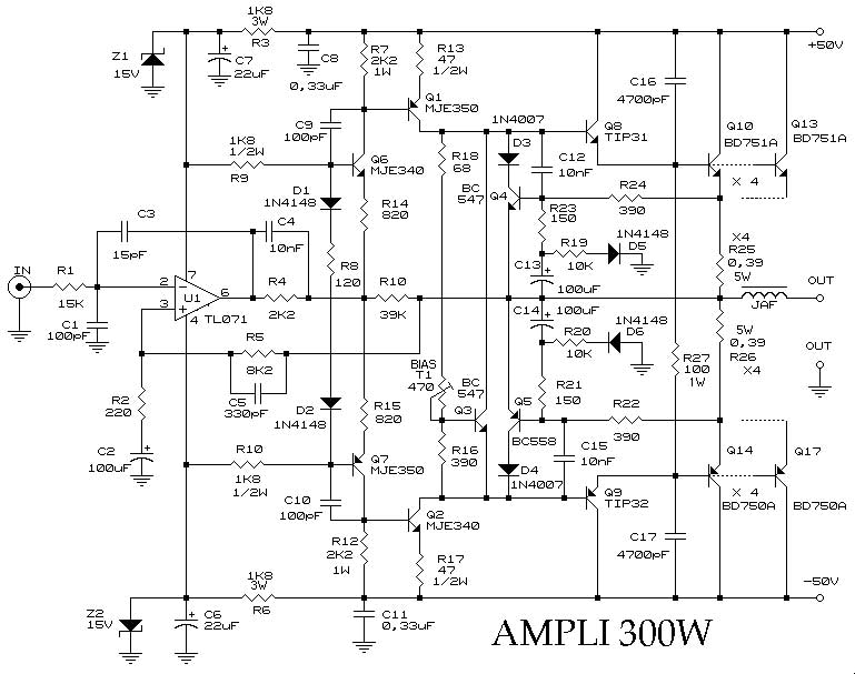
Whats this do?? lol
Whats this do?? lol
Attachments
are you askin me?? lol
http://web.tiscali.it/audiofanatic3/Tipo/Stato_solido/pic_finaliSS/150W_BDY25.jpg
is where it came from... its linked to on the diyaudio links page. . lol
http://web.tiscali.it/audiofanatic3/Tipo/Stato_solido/pic_finaliSS/150W_BDY25.jpg
is where it came from... its linked to on the diyaudio links page. . lol

Diode said:Hey,
Great design especially for its simplicity!!!! My question.... What are the extra .22Ohm resistors doing there before the main output besides blowing up? No, for real, what are they for?
Chris
Setting bias. The output stage is quasi-complementary
It is Verboten for me to access that site from this server.
No I wasn't asking you specifically.... I was being serious AND sarcastic. There's no way that those 2 .22 ohm resistors could take the output of a high power amp and survive. At least I can't fathom that..... You mentioned that you had spent $100 on transformers and were considering buying more? If I'm wrong, I'm sorry but use the next $100 for transistors and perf board!!! I'm looking at building a 500W amp and I don't think that all of the transistors will cost $100 and there's 7 per rail plus the others!!! I understand cheap and simple real well. That's my motivation behind the amp I want to build. I'd consider Anthony Holton's amp but FET's are a real pain for me to get at a reasonable price without huge quantity. Too much money for me. Dude, Good luck with your endevour. You can check out my thread "500W amp" and look at what I'm trying! Look at Blackwidowaudio.com I think that's the site or do a search on Google.com for blackwidow audio. He ahs a 60W circuit that is simple and easy AND probably could be tweaked for a bit more power. Just a thought. 
Later,
Chris
No I wasn't asking you specifically.... I was being serious AND sarcastic. There's no way that those 2 .22 ohm resistors could take the output of a high power amp and survive. At least I can't fathom that..... You mentioned that you had spent $100 on transformers and were considering buying more? If I'm wrong, I'm sorry but use the next $100 for transistors and perf board!!!
I'm looking at building a 500W amp and I don't think that all of the transistors will cost $100 and there's 7 per rail plus the others!!! I understand cheap and simple real well. That's my motivation behind the amp I want to build. I'd consider Anthony Holton's amp but FET's are a real pain for me to get at a reasonable price without huge quantity. Too much money for me. Dude, Good luck with your endevour. You can check out my thread "500W amp" and look at what I'm trying! Look at Blackwidowaudio.com I think that's the site or do a search on Google.com for blackwidow audio. He ahs a 60W circuit that is simple and easy AND probably could be tweaked for a bit more power. Just a thought. Later,
Chris
"There's no way that those 2 .22 ohm resistors could take the output of a high power amp and survive. "
A sine wave is off 50% of the time. If we use a 10W part it will handle 14.14W on half-cycles, 14.14/.22=64.27(I^2), P=(I^2)R, 64.27 * 4R = 257W
On normal program material it will probably handle twice this amount, or 500W
A sine wave is off 50% of the time. If we use a 10W part it will handle 14.14W on half-cycles, 14.14/.22=64.27(I^2), P=(I^2)R, 64.27 * 4R = 257W
On normal program material it will probably handle twice this amount, or 500W
Hey man,
I don't know what you have access to but in the US, we have pawn shops or used shops. Look at them and see what they have. Also look and see if a local repair shop has a junk amp or guitar amp that is too old or expensive to fix and see if there might be a cheap transformer in there to use! Just a thought. I am a technician in a guitar shop and I fix guitar amps and the like. We have a bunch of junk amps that I can get transformers from and filter caps too, but not always......
Hope those ideas help!
Chris
- Status
- This old topic is closed. If you want to reopen this topic, contact a moderator using the "Report Post" button.
- Home
- Amplifiers
- Solid State
- +-25volts = ??Watts bridged??