Does changing the value of R2 require a change in the value of C2? Jason talked about corner frequency changes with input resistors.
you can but not absolutely necessary...
22ufd and 47k corners at 0.15hz, why would anyone want that?
2.2uf and 47k corners at 1.5 hz, still quite low...
1ufd and 47k corners at 3.4 hz still quite low....
my rule of thumb for coupling caps, use the smallest value you can get away with...
")
I'm used to seeing polar caps in series with opposing polarities if used on inputs in schematics (Slone's books).
instead of that , film caps are better, today you can easily buy those...
i was given a tube preamp wherein the cathode bypass cap was reversed in polarity, the positive end was connected to the ground bus instead....but lo and behold, the preamp runs fine even with the cap reversed...i never bothered to correct it...it was working fine...
you can but not absolutely necessary...
22ufd and 47k corners at 0.15hz, why would anyone want that?
2.2uf and 47k corners at 1.5 hz, still quite low...
1ufd and 47k corners at 3.4 hz still quite low....
my rule of thumb for coupling caps, use the smallest value you can get away with...
0.15hz seems almost dangerous for speakers. Not far off DC coupled. I agree about using film caps.
There are test results posted on this Forum that confirm some better topologies for electrolytic capacitors.I'm used to seeing polar caps in series with opposing polarities if used on inputs in schematics.............
Read the papers.
And I don't remember the Author's names, nor the posts they appeared in.
Upto 10uF are feasible in plastic film, beyond 1uF most would go over to using electrolytic.
Last edited:
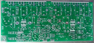
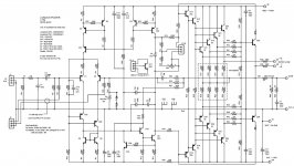
One problem with threads like this is that picks get lost in back pages making it difficult to discuss. I am attaching pics of the empty boards so you can see the part numbers along with their intended values. I am also attaching the schematic.
Now to answer some questions.
C2 shows polar on the schematic but calls for bi-polar on the silkscreen and in the docs. I used bi-polar there. C4 calls for 2m2-4m7 and the docs suggest largest that will fit. I started with 4700uF which caused the offset to take forever to settle.
I did add 47pf caps to the b-c of each predriver. Oscillation is still there. Next?
Thanks, Terry
Now to answer some questions.
Are C2 and C4 non polar caps?
C2 shows polar on the schematic but calls for bi-polar on the silkscreen and in the docs. I used bi-polar there. C4 calls for 2m2-4m7 and the docs suggest largest that will fit. I started with 4700uF which caused the offset to take forever to settle.
I thought to change R2 to 47k5 to 33k because OS had suggested changing R16 to 33k from 47k5 and I thought that may be what caused the offset to change. I have not tried changing it on the board yet.R2 and R16 are required to be identical, R2 being connected to psu ground is also at ac ground, R16 is also connected to the virtual ground formed at the output of the amp, with no input signal it is at ac ground or zero volts...
what happened when you changed R2 to 33k is offset this balance in such a way that the output node is closer to zero volts than otherwise...this means that the imbalance is happening elsewhere.....
I don't understand what corner frequencies means. Just following instructions.0.15hz seems almost dangerous for speakers. Not far off DC coupled. I agree about using film caps.
I did add 47pf caps to the b-c of each predriver. Oscillation is still there. Next?
Thanks, Terry
Attachments
Some would call it roll-off frequency, others would call it the F-3dB frequency.I don't understand what corner frequencies means.
It is calculated from the F-3dB = 1 / {2 pi R C}
Someone correct me if I'm wrong please. The input capacitor is there to stop DC from being amplified, otherwise the cone flies out of your speaker. It acts as a high pass crossover. The corner frequency is the frequency that it starts to pass signal at. Changing the size of the cap or the resistor with it changes that frequency.
The post744 shows C2=22uF and C4= 2m2F to 4m7F
Both of these extend the pass band far too low for audio.
C2 sets the F-3dB to 0.15Hz
This is about a decade lower than it could usefully be. Try 2u2F instead. Use a polypropylene film and either metallised or foil.
To match C2, C4 needs to be changed to C2*R2*sqrt(2)/R15 = 2u2*47500*1.4/1000 = 148uF or a bit larger. Try 150uF or 220uF
Add two more diodes across C4, but inverted to pass in the other direction.
1n4148 will do, they have a 75V reverse capability.
C1 = 100pF is set too low, it lets in far too much VHF.
F-3dB = 1/{2Pi100r*100pF} = 16MHz
It could be increased by a decade and still be too low , F-3dB = 1.6Mhz
Try 1n5F or 2n2F
EXCEPT if you know you have a very high Source Impedance.
A Buffer is likely to be <200r, giving a total Rs of 200r from the Buffer and 100r due to R1.
F-3dB becomes 354kHz using 1n5F or 240kHz using 2n2F
Yes, the two capacitors combined with the two resistors set the Pass Band of the amplifier. Lopass = R1C1 and Hipass = C2R2. Note that Ost labeled them and thought of them as filter pairs.Someone correct me if I'm wrong please. The input capacitor is there to stop DC from being amplified, otherwise the cone flies out of your speaker. It acts as a high pass crossover. The corner frequency is the frequency that it starts to pass signal at. Changing the size of the cap or the resistor with it changes that frequency.
Set them as narrow as possible without removing any of the wanted audio signal. A Treble only amplifier is different from a Mid only amplifier is different from a wideband amplifier.
There is much debate on how close to the traditional 20Hz to 20kHz the Pass Band can be, but there is some consensus that allowing one decade below 20Hz and one decade above 20kHz, i.e. 2Hz to 200kHz, does not make any audible difference to the final audio signal you are passing for a wideband speaker.
Last edited:
pF = pico Farad
pf = pico fempto
Me and many others have posted the same information very many times.
I just cannot understand why so many do so little research for their projects.
Is that the way the "many" approach life. Let's muck along and forget the consequences.
pf = pico fempto
Me and many others have posted the same information very many times.
I just cannot understand why so many do so little research for their projects.
Is that the way the "many" approach life. Let's muck along and forget the consequences.
Last edited:
We need to figure out what to research before we actually do any research. When we're building what's supposed to be a working amplifier from a schematic most would figure the research is already done. I know myself and I also suspect Terry learn quickly when things go wrong and we're scrambling to figure out why.
Which part are you claiming you don't understand this time?
The post744 shows C2=22uF and C4= 2m2F to 4m7F
Both of these extend the pass band far too low for audio.
C2 sets the F-3dB to 0.15Hz
This is about a decade lower than it could usefully be. Try 2u2F instead. Use a polypropylene film and either metallised or foil.
To match C2, C4 needs to be changed to C2*R2*sqrt(2)/R15 = 2u2*47500*1.4/1000 = 148uF or a bit larger. Try 150uF or 220uF
Add two more diodes across C4, but inverted to pass in the other direction.
1n4148 will do, they have a 75V reverse capability.
C1 = 100pF is set too low, it lets in far too much VHF.
F-3dB = 1/{2Pi100r*100pF} = 16MHz
It could be increased by a decade and still be too low , F-3dB = 1.6Mhz
Try 1n5F or 2n2F
EXCEPT if you know you have a very high Source Impedance.
A Buffer is likely to be <200r, giving a total Rs of 200r from the Buffer and 100r due to R1.
F-3dB becomes 354kHz using 1n5F or 240kHz using 2n2F
Straining gnats once again
Add two more diodes across C4, but inverted to pass in the other direction.
1n4148 will do, they have a 75V reverse capability.
i am sure that Terry had successfully built amps that did not use diodes across C4, i built a lot of amps without it.....additional diodes will cause huge output offsets as those diodes are conducting in the forward direction, drawing current from the base of the pnp input ltp..
like OS said, increasing the output base stoppers from 2.2 ohms to 4.7 or up to 10 ohms can be tried...
remove Q12 and R14......not absolutely required...
remove C16 and change R37 to 100 ohm 1/8 watt resistor
remove C19, C12 to be jumpered, R57 removed...
above simplifies your circuit....and hopefully it works...
We need to figure out what to research before we actually do any research. When we're building what's supposed to be a working amplifier from a schematic most would figure the research is already done. I know myself and I also suspect Terry learn quickly when things go wrong and we're scrambling to figure out why.
not this amp, this amp it turns out has a lot of bugs that need fixing...
if you were cloning leach amps, you will have better chances of success...
@Terry, if you can entrust to me the gerber files, i can ask some of the lay-out guys in a local forum to remake the gerbers with my corrections....you can email them to me...
Sure, they are also free to download on Struth's website. However, don't you think we should get a working model before we invest any more money in pcb's?
If the latest suggestions don't prove to be successful, I may try swapping out the outputs to MJL4281/4302 and see if that helps cease the oscillation.
Thanks, Terry
EDIT: I just checked and the free download doesn't include Gerbers. I'm not sure if I can legally share them. I will check.
Last edited:
I don't think you are right....................additional diodes will cause huge output offsets as those diodes are conducting in the forward direction, drawing current from the base of the pnp input ltp.....................
I have measured the DC voltage across the DC blocking capacitor of a properly operating Power Amplifier and the voltage is roughly the same or less than is measurable across the input resistor. Vin is typically 20mVdc to 200mVdc. A base current of 2uA through 51k is 102mVdc.
The current passing a signal diode that is cold, in the forward direction, is negligible. I generally use just one diode in each direction rather than the two shown here. The diodes DO NOT change the output offset.
There is an additional advantage to using two diodes in each direction. The series pair reduces the diode capacitance. This capacitance is non linear in that it varies with the instantaneous applied voltage due to the AC signal.
Halved capacitance may result in lower measurable distortion.
Last edited:
- Status
- This old topic is closed. If you want to reopen this topic, contact a moderator using the "Report Post" button.
- Home
- Amplifiers
- Solid State
- 250w 8ohm amplifier