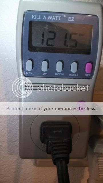
Sorry, I should have pointed out that my transformer is rated for 115V mains. My house mains run at 119-122VAC most of the time. I just checked and they are at 121.2V right now. The rails on my Superamp run from +/-90V ;at idle, down to about +/- 86V at full power depending what time of the day it is.
Hi Guys
The 90V should be 80V - a 10V typo.
Brlmat, the circuits recommended will function very well scaled up to whatever power you need.
DC protection for the speaker is easy to add using a few BJTs and a relay powered from 12V. Lots of standard circuits out there and even kits and modules.
Protection for the amp happens by way of fuses on each rail and then SOA circuits. The latter are usually just two BJTs with some Rs, Cs and sometimes 2-4 diodes. Ed Cherry had an article in ETI about designing these circuits and calculating values for whatever amp you were installing it into.
Input signal limiting or compression can be implemented several ways. The fact such a circuit might be required strongly indicates how biamping your main cabinet could save you blown tweeters. The high-frequency signal rides atop the bass signal, so it is the high-f part that gets clipped first and fries your tweeters. If the woofer had its own amp, you would never clip the tweeter amp.
Otherwise, signal limiters come as clippers or as gain reducers, or as passive signal reducers. Clippers are just diodes, but this can be elaborated into quite complex variable level circuitry. The other two options involve a "side chain" circuit that measures signal level and creates a comperrion control voltage that either varies gain of a transconductance stage in the signal path - potentially noisy - or that causes a jfet or LDR to cut signal as part of an attenuation network.
Other methods involve monitoring the differential signal across the amplifier's diff-amp bases, and using this to control the incoming signal level through attenuation. In this method, actual distortion in the amp is detected and signals reduced to reduce the distortion.
Have fun
Kevin O'Connor
Aah, it makes sense now. Anyway, my amp is rated for 220V mains (should be 230 as this is the average, but anyway, it drops sometimes). So back to amps. Are the protections easily adaptable or should I go with an amp with built in protections? I would also like some kind of input-output-comparator as I crank the volume too high sometime and there comes a louder song and there goes my speaker...
protection add on's
Evening to you, the answer to your question is yes these circuits are easy to add to any amplifier with the right circuit fitting.. some can be added via using the amps supply rails or evening different supply rails.. all in all these units save the speakers from getting roasted
Aah, it makes sense now. Anyway, my amp is rated for 220V mains (should be 230 as this is the average, but anyway, it drops sometimes). So back to amps. Are the protections easily adaptable or should I go with an amp with built in protections? I would also like some kind of input-output-comparator as I crank the volume too high sometime and there comes a louder song and there goes my speaker...
Evening to you, the answer to your question is yes these circuits are easy to add to any amplifier with the right circuit fitting.. some can be added via using the amps supply rails or evening different supply rails.. all in all these units save the speakers from getting roasted
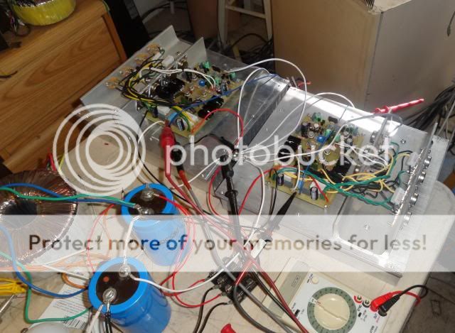
I have been playing my Superamp most of the day. I had an strange oscillation or feedback problem that I was trying to solve when all of sudden it went away. Anyway, I guess the output is around 145w into 8 ohms Maybe not enough for what you are looking for. I've been playing into 4 ohms for most of the day and it doesn't break a sweat. The heatsinks are barely warm.

Sorry, I should have pointed out that my transformer is rated for 115V mains. My house mains run at 119-122VAC most of the time. I just checked and they are at 121.2V right now. The rails on my Superamp run from +/-90V ;at idle, down to about +/- 86V at full power depending what time of the day it is.
Hi Terry:
115v rated 55-0-55 running at actual mains of 122 should do about (55/115*122=) 58.34vac
58.34vac x 1.414142 = 82.5vdc. Then you drop about 0.7 to 1.2volts across the Bridge/Diodes, this gets you to about 81.5vdc. Still does not make 90vdc.
On the other hand, 65-0-65 gets you +/- 90vdc.
or perhaps your transformer has 115vac input and also 100vac input and you are running it at 100vac input. That would be 55vac/100*115 = 63.25vac
63.25 vac gives you about 89vdc rails on 115v mains ... but then at 122 mains, it gives you 55/100*122 = 67vac rails and about 95vdc rails.
So I am perpexled how you get 90vdc rails.
Can you please measure the vac on your secs? I bet it is no where near 55vac.
Also at 90vdc dropping to 86 under load, you are getting OVER 400 watts RMS into 8 ohms!
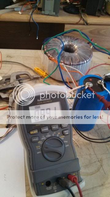
I am using this transformer.
Here is a picture of it at idle.
Pic of what the mains are at the time.
There are three wires for the mains, black and red for 115v or black and yellow for 230v. The output has 8 wires. Two pairs for 55v and two pairs for 15V. I have the 55v output wires in parallel and not using the 15v windings.
I ran it hard a couple of times today and the rails will actually drop to 84.8V at some loud bassy passages into 4ohms. It was very loud through my JBL's

Here is a picture of it at idle.

Pic of what the mains are at the time.

There are three wires for the mains, black and red for 115v or black and yellow for 230v. The output has 8 wires. Two pairs for 55v and two pairs for 15V. I have the 55v output wires in parallel and not using the 15v windings.
I ran it hard a couple of times today and the rails will actually drop to 84.8V at some loud bassy passages into 4ohms. It was very loud through my JBL's

Actually, I just did a search and found the original thread from when I first bought the transformer. It is not the one I linked to. I still think I bought it from Antek though. I'm just thankful to finally be able to use it.
Actually, I just did a search and found the original thread from when I first bought the transformer. It is not the one I linked to. I still think I bought it from Antek though. I'm just thankful to finally be able to use it.
Nice set up Terry
Listen, I just wanted you to measure the secondary's off the transformer. Rest I believed you anyway

leach superamp
If all is fine just leave as is and pop things in to it's case
I don't know what caused it. I suddenly disappeared and has not returned. I am going to replace the devices in the front end, mainly because I didn't match them when I replaced them andthe offset is greater than the other channel. Right now it is playing nice.
If all is fine just leave as is and pop things in to it's case
leach superamp
Hi Terry, the o/p power is about right given the ac volts across the o/p..just one thing to add, on your filter caps add some discharging resistors of say 4k7 to 10k at 4w and 220nf cap's this will add bleeding away the voltage at each power down.
I have been playing my Superamp most of the day. I had an strange oscillation or feedback problem that I was trying to solve when all of sudden it went away. Anyway, I guess the output is around 145w into 8 ohms Maybe not enough for what you are looking for. I've been playing into 4 ohms for most of the day and it doesn't break a sweat. The heatsinks are barely warm.
Hi Terry, the o/p power is about right given the ac volts across the o/p..just one thing to add, on your filter caps add some discharging resistors of say 4k7 to 10k at 4w and 220nf cap's this will add bleeding away the voltage at each power down.
Do the sums properly.K-amps, i have no idea how he got that result. I mean, in theory, 55Vac is actually 55*sqrt(2)=~77Vdc.
So it is also when measured.
Use actual values of rated mains voltage, current value of mains voltage, regulation of transformer, current draw on the PSU, etc.
- Status
- This old topic is closed. If you want to reopen this topic, contact a moderator using the "Report Post" button.
- Home
- Amplifiers
- Solid State
- 250w 8ohm amplifier