I'm surprised they teach French in US!
I didn't grow up in the US. French wasn't illegal where I grew up...
") In fact, growing up, I spent many summers camping in Provence. I was 25 years old when I moved to the US for grad school. Kinda got stuck... One of these days I plan to find myself living in the True North, though.
In fact, growing up, I spent many summers camping in Provence. I was 25 years old when I moved to the US for grad school. Kinda got stuck... One of these days I plan to find myself living in the True North, though.Hi Tom, Last year I constructed copies of your regs for comparison with my existing designs. Yours are smaller, cheaper, easier to build and work every bit as well as my grossly over-designed behemoths.
What a neat little implementation on the 3080's adj line.. I also conducted fairly rigorous testing with various caps and current draws, these showed your regs to be stable with 200uF output caps @ 420V /150ma loadings.
I would suggest that people not substitute for the STW12NK95Z when using input voltages >480V.
Another caveat is that I always use NTC's on the mains input to the trans to reduce the Pdiss of the FET's during start-up.
How long your thread has become: (hope there wasn't anything too interesting in the intervening pages)!
Thanks for your efforts. Regards, Glens
Oh, cool!! Thank you for sharing. It's always good to hear that others are able to reproduce my circuits and are able to enjoy the fruits of my labor (and their own too).
Thanks,
~Tom
Davs Bjarne,
I've tested the regulator at both high and low currents. In addition to various torture tests to simulate the effects of loose connections in tube sockets, etc., I tested the transient response of the regulator at various output currents. I have not found any issues.
I have no reservations about using the 21st Century Maida Regulator at low currents.
You can see some of my measurements in post #1. Also, check out my plot of the output impedance.
Hygge,
~Tom
Last edited:
problem
Tom,
I tried to use your Maida regulator for a 6N7 driver stage (300V @ 12mA, 75R as current limiter).
Until now, there was a rc filter type installed using the CT and the ground ( For output tubes, I have a bridge for a 600V line filter, the "negative side"
at the ground).
But the regulator cannot reach the 300V (even if the raw DC is around 400V). Should I use a different wiring scheme?
Thanks
Which values are you using for R3 and R9?
Would you measure the following voltages: Input voltage measured at the input connector, output voltage measured at the output connector. If possible, measure the input voltage using an oscilloscope. Note the lowest voltage on the measurement (the bottom of the ripple voltage). Repeat the measurement with the load disconnected from the Maida Regulator.
What is the voltage from gate to source on Q1?
Would you post a complete schematic of your circuit? I'm having a hard time visualizing your circuit from your description.
You're the first to have trouble with this regulator, so I'm rather curious to figure out what's going on.
If I was to make a shot-in-the-dark guess, I'd say you're getting current through the zener diode D2 and its series resistor R1, but the regulator IC never turns on. This could happen if you forgot to populate R2, D4 was reversed or shorted, or R3 disconnected.
Another thing you can try is the following:
* Disconnect the Maida Reg completely from the tube amp and power transformer.
* Short out R9 with a short piece of wire or a test lead.
* Connect the input of the regulator to a lab supply providing 15~20 V.
* Measure the output voltage. This should be 1.0 V +/- 2 %.
* If you don't get 1.0 V on the output, de-solder R3 and connect the lab supply to pin 5 of the regulator IC.
* Measure Vout = 1.0 V. If no Vout, the regulator IC either isn't connected or is defective. If Vout under this condition is significantly higher than 1.0 V, D3 is likely reversed (or defective).
~Tom
Using the center tap as a "positive" may work or it may not. It depends on how the rest of the system. If you post a schematic, I can help out.
It sounds like a number of changes were made at the same time. Changing R3 and R9 should not break the regulator. With R3 = 75 ohm and R9 = 150 kOhm, I would expect the regulator to be able to provide 300 V at up to 45 mA. I'd go back to the latest working configuration but leave R3 and R9 at their current values. If the regulator still doesn't behave, let's do some debugging.
Double-check that R3 is indeed 75 ohm (measure it).
~Tom
Tomchr, I too had some ideas about how to make some improvements in the Maida type regulator. So I decided to do a search on the state of the art for HV regulators, and up popped your design. Darn you, sir!
No, really, quite nice.
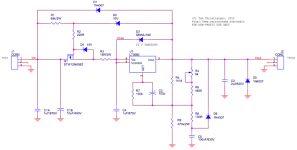
It has occurred to me that all three-terminal regulator designs employ a voltage divider network between output and ground. The division point is directly or at least tightly connected to the (in this case SET) pin of the regulator. (Your design employs a tight connection through R7 and C3.) In general, the ripple rejection and output impedance of these regulators benefit when we maximize the attenuation of the divider.
I did some simulations of your original design (Vout_orig), one with some modest value modifications (Vout_mod) that I believe would fit on your PCB, and one which is a “go for broke” approach (Vout_...guess?) where the attenuation is essentially infinite. The simulations are for startup, ripple rejection and output impedance (Zout).
The startup is identical in all three circuits, but the ripple and output impedance in the “mod” and “go for broke” designs seem to show significant performance improvements at and below about 2KHz.
I‘d be interested in your thoughts.
No, really, quite nice.
It has occurred to me that all three-terminal regulator designs employ a voltage divider network between output and ground. The division point is directly or at least tightly connected to the (in this case SET) pin of the regulator. (Your design employs a tight connection through R7 and C3.) In general, the ripple rejection and output impedance of these regulators benefit when we maximize the attenuation of the divider.
I did some simulations of your original design (Vout_orig), one with some modest value modifications (Vout_mod) that I believe would fit on your PCB, and one which is a “go for broke” approach (Vout_...guess?) where the attenuation is essentially infinite. The simulations are for startup, ripple rejection and output impedance (Zout).
The startup is identical in all three circuits, but the ripple and output impedance in the “mod” and “go for broke” designs seem to show significant performance improvements at and below about 2KHz.
I‘d be interested in your thoughts.
Attachments
Tomchr, I too had some ideas about how to make some improvements in the Maida type regulator. So I decided to do a search on the state of the art for HV regulators, and up popped your design. Darn you, sir!
Good to hear I'm famous on the internet... In general, the ripple rejection and output impedance of these regulators benefit when we maximize the attenuation of the divider.
That is an excellent idea. I like your "mod" circuit, i.e. R7 = 1 Mohm, C3 = 1 uF. I may have to try that.
Of course, with the higher voltage drop across R7, the output voltage won't be the nice 2*R9/1000, but 10~11 V off. However, for voltages commonly used in tube circuits, the difference is negligible and I could just widen the adjustment range on the trimpot.
Thanks for bringing this up. I'll keep your suggestions in mind. I'm always looking to improve.
~Tom
Heya Tom,
I am also using the Maida regulator onto a phono-amplifier. I will test next weekend how the regulator will preform. The voltages are all ok. Really love your work.
I am also considering to build your 300B amplifier, but first I got to finish some of the long-running projects
Kind regards,
Fokko
I am also using the Maida regulator onto a phono-amplifier. I will test next weekend how the regulator will preform. The voltages are all ok. Really love your work.
An externally hosted image should be here but it was not working when we last tested it.
I am also considering to build your 300B amplifier, but first I got to finish some of the long-running projects
An externally hosted image should be here but it was not working when we last tested it.
Kind regards,
Fokko
Of course, with the higher voltage drop across R7, the output voltage won't be the nice 2*R9/1000, but 10~11 V off.
How do you get 2*R9/1000? If we define R456 = R5 || (R4 + R6), I calculate the output voltage to be 10uA * R7 * ( 1 + R9/R456 ).
How do you get 2*R9/1000? If we define R456 = R5 || (R4 + R6), I calculate the output voltage to be 10uA * R7 * ( 1 + R9/R456 ).
The IC provides 10 uA through the SET pin. This sets up 1.0 V across R7. The IC has unity gain between the SET pin and the OUT pin, hence, it will maintain 1.0 V across R456. This sets up a current of 1/R456 in R456. This current is adjusted by R6 to be 2.0 mA. This current flows through R9 to ground. Hence, the output voltage is Vout = 2E-3*R9+1 ... or for Vout >> 1, Vout = 2*R9/1000.
I do admit to obscuring the math with the R9/1000, but it makes life so much easier. Output voltage = 2 * R9 in kOhm. 200 kOhm --> 400 V.
I was thinking that one drawback of increasing R7 might be higher drop-out voltage. I.e. the difference between Vin and Vout might need to be larger with your values. In 99 % of tube circuits there's plenty of voltage to spare, so it's probably not an issue. But that's something to keep in mind. I'll have to play with it...
~Tom
I am also using the Maida regulator onto a phono-amplifier. I will test next weekend how the regulator will preform. The voltages are all ok. Really love your work.
Sweet. Thanks for posting!
I am also considering to build your 300B amplifier, but first I got to finish some of the long-running projects
Why? I start new projects without finishing the old ones all the time...

No worries. I have no plans of going away.
~Tom
The IC provides 10 uA through the SET pin. This sets up 1.0 V across R7. The IC has unity gain between the SET pin and the OUT pin, hence, it will maintain 1.0 V across R456. This sets up a current of 1/R456 in R456. This current is adjusted by R6 to be 2.0 mA. This current flows through R9 to ground. Hence, the output voltage is Vout = 2E-3*R9+1 ... or for Vout >> 1, Vout = 2*R9/1000.
Ah! I didn't realize that you required the current to be adjusted by R6 to 2mA. Do you actually measure 2mA somewhere? Why not just adjust the pot until you get the output voltage you want? Pre-calculate values of course so you're sure the pot gives you the range you need.
I was thinking that one drawback of increasing R7 might be higher drop-out voltage. I.e. the difference between Vin and Vout might need to be larger with your values. In 99 % of tube circuits there's plenty of voltage to spare, so it's probably not an issue. But that's something to keep in mind. I'll have to play with it...
I don't see how this affects the Vin - Vout requirements. For a given Vout, Vin is unchanged, and so is their difference. All that has happened is that the attenuator voltage has been moved from 1 to 10V below Vout. I don't see any cause for worry there. Maybe you can elaborate on your concern?
Ah! I didn't realize that you required the current to be adjusted by R6 to 2mA. Do you actually measure 2mA somewhere? Why not just adjust the pot until you get the output voltage you want?
The adjustment procedure is simple: Crank the pot until you get the voltage you want. The center value will be 2*R9/1000. At this value, 2 mA flows in R9 (hence, by Kirchoff's law also in R456 (neglecting the 10 uA flowing in R7)).
In addition to eliminating the need for an insanely large resistance of R7, and associated issues with leakage currents, the 2 mA serves two purposes.
1) It keeps the regulator happy. It requires 1 mA of output current to regulate properly.
2) It keeps D2 biased, hence, insures that the cascode (Q1) is happy.
I don't see how this affects the Vin - Vout requirements. For a given Vout, Vin is unchanged, and so is their difference. All that has happened is that the attenuator voltage has been moved from 1 to 10V below Vout. I don't see any cause for worry there. Maybe you can elaborate on your concern?
After I submitted my previous response, I ended up at the same conclusion as you. I don't think there is an issue with the drop-out voltage. It's just something I'd verify before committing to the BOM change.
Also, the start-up time with R7 = 1 Mohm, C3 = 1 uF will be one tenth that of my original circuit. This may impact the survivability of Q1 when starting up into a capacitive load. Again, this is a hunch/intuition in addition to learnings from past experience. I would need to run some sims and try it out before committing to a BOM change. I'm not saying it wouldn't work. I'm just saying that I would prefer to test it before committing to it and pointing people in that direction.
This shouldn't prevent anybody from trying it out, though.
~Tom
Last edited:
I agree that it's fine to have the output source approximately 2mA and to adjust the pot to get the desired output voltage. For a 2*R9/1000 Vout, there will be two deviations from the 2mA output current through the driver path: a .5% error due to the 10uA Iset current, and an error of about 2mA * (the voltage across R7) / Vout.
I'll agree with your start-up caution. But my sim showed that the start up time is unchanged in all three variations. I would expect this since I kept the R7 C3 time constant at 1 second. Of course, I could have made a mistake. Is there a reason I'm missing that causes you to expect a 10x increase in start up time?
If you'd like, I can post for your perusal the .asc files I used in LTSpiceIV sims.
For a 2*R9/1000 Vout, there will be two deviations from the 2mA output current through the driver path: a .5% error due to the 10uA Iset current, and an error of about 2mA * (the voltage across R7) / Vout.
Not to mention the 1 % tolerance of R7, and 5 % on R9. Resistor tolerances tend to dominate in the error budget. And you know... That's why the trimpot is there.
I would expect this since I kept the R7 C3 time constant at 1 second. Of course, I could have made a mistake. Is there a reason I'm missing that causes you to expect a 10x increase in start up time?
The start-up time of the regulator IC is set by the 10 uA Iset current and C3. The start-up time: t = C*V/I. But for the complete regulator, there's more to it than that, as there is also a current path through D2 (the zener for the cascode biasing).
If you'd like, I can post for your perusal the .asc files I used in LTSpiceIV sims.
I have the .asc file, actually. I just haven't had time to play with your suggested component changes, yet. I have quite a few irons in the fire here... I see no reason your changes wouldn't work. I'd go with R7 = 1 Mohm, 1 % and C3 = 1 uF. Multiply R4, R5, and R6 by 10. That should be a good starting point.
PS: My math tends to be the back-of-the-envelope type. Get the job done. For multi-digit precision, I rely on simulation and lab results.
~Tom
Sounds good! I'm very interested to hear of your results when you get the time.
If we put aside the effect of the D2 current, I believe that you will find that the following is true:
The start-up time of the regulator IC is set by the 10 uA Iset current and C3. The start-up time: t = C*V/I.
If we put aside the effect of the D2 current, I believe that you will find that the following is true:
Regarding startup, the governing equation is Vout = FOV * ( 1 - e^(-t/(R7*C3) ), where FOV is the Final Output Voltage and is equal to Iset * R7 * ( 1 + R9/R456 ).
As long as the R7*C3 product is kept constant, the start up time from 0% to any fixed percentage of the FOV should not change.
Of course you will probably want to juggle resistor values to keep the FOV constant. But even if you don't, if the FOV remains one that the regulator can reach and maintain, the time to that fixed percentage of FOV should not change.
- Home
- Vendor's Bazaar
- 21st Century Maida Regulator