Thanks for the through response!. I guess i am preordering.
Thanks. I should include that design template on my website. It would make many people's lives easier. BTW, the calculation above assume no voltage drop across the rectifier. I assume that if someone goes through the trouble of regulating the supply, they probably aren't using a tube rectifier. And silicon doesn't have much of a drop.
With a tube rectifier, I'd look up how much secondary voltage is needed at a given output current to get the voltage required by the regulator. You can generally find this information in the datasheets for the tubes.
With the 500 mA idle current of your amp, what's the peak current? With push-pull, I'd think the current would be relatively constant 500 mA, but I have no experience with push-pull. You may consider using one regulator per channel. They can be mounted on the same heat sink if need be as the heat sink only cares about the average power, not peak power.
~Tom
500 mA relatively constant current shouldn't be a problem. Too much beyond that, the regulator IC would probably start getting rather hot. It uses copper planes on the board for heat sinking so I need to measure the thermal performance of the fabricated boards before I can provide any guidelines.
The max current is determined by the voltage drop across zener diode D2, R3, and the Vgs of Q1. These components determine how much voltage is available across the regulator IC. The IC needs at least 1.6 V to regulate properly. But going significantly beyond that burns a lot of power in the IC. So find some values that work for a 2-ish V drop at idle.
So V(D2)-V(Vgs)-V(IC) = V(R3)
V(R3) 10 - 5 - 2 = 3
I(R3) = 0.5 A --> R3 = 3=0.5 = 6 Ohm. I'd pick R3 = 5.6 Ohm.
This would result in 10-5-5.6*0.5 = 2.2 V across the IC. Sweet!
This results in the following power dissipation:
P(R3) = 0.5^2 * 5.6 = 1.4 W (a 3 W type would be marginal here, I'd use a 5 W type)
P(IC) = V(IC)*I(IC) = 2.2*0.5 = 1.1 W
I'm burning about 0.5 W in the IC in my prototype regulator. But my prototype does not have thermal vias under the IC, hence, has much worse thermal performance than the final board will have. I'm measuring about 25 deg C of temperature rise on the regulator IC. With 1.1 W, you'd get twice that. But with the better thermal performance of the board, I'm guessing you'll end up at a comfortable 50-ish deg C IC case temperature at 25 deg C ambient. That's a guess, though. Using two regulator boards would reduce the power dissipated in R3 and the IC by a factor of two. Hence, my recommendation to use one regulator for each channel.
~Tom
Last edited:
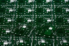
Boards are in
The boards arrived about 30 minutes ago. I've sold about half of them so if you are thinking about buying one, you may want to convert thoughts into action... I can, of course, always order more if there is sufficient interest.
~Tom
The boards arrived about 30 minutes ago. I've sold about half of them so if you are thinking about buying one, you may want to convert thoughts into action... I can, of course, always order more if there is sufficient interest.
~Tom
Attachments
Hi Paul!
Why TO220?
Dissipation only 0.4-0.5W.
Farnell stocking SMD version (EU stock/UK stock).
LT3080EST#PBF - LINEAR TECHNOLOGY - IC, LDO REG, ADJ, 1.1A, SOT223 | Farnell United Kingdom
Why TO220?
Dissipation only 0.4-0.5W.
Farnell stocking SMD version (EU stock/UK stock).
LT3080EST#PBF - LINEAR TECHNOLOGY - IC, LDO REG, ADJ, 1.1A, SOT223 | Farnell United Kingdom
You'll need the surf mount DD-PAK 5-pin package for this board. The TO220 will NOT fit.
I am considering offering a partially assembled board for sale. It would have all the SMD parts soldered on and some limited testing performed to ensure that the parts were soldered down correctly. However, it will be significantly more cost effective for people to purchase and solder down their own parts. At least if you don't charge for your own assembly time.
~Tom
Just responded to your email. Based on your schematic, I estimate that your amp draws about 255 mA per channel. Allowing a bit of margin (20-ish percent), this means the Maida Regulator will have to supply 300 mA or so per channel.
You could probably run two channels on one regulator, but I think it'd be pushing the thermal limits pretty hard. I would split it into two regulators - one per channel.
Have a look at Post #63 for how to calculate R3 and the heat sink.
~Tom
You could probably run two channels on one regulator, but I think it'd be pushing the thermal limits pretty hard. I would split it into two regulators - one per channel.
Have a look at Post #63 for how to calculate R3 and the heat sink.
~Tom
Q1 is actually a cascode. It drops the input voltage to roughly Vout-5 V. The pass transistor in this regulator design is the pass transistor integrated on the LT3080.
At higher output currents, significant power is dissipated in R3. That's one limiting factor.
Also, at higher output currents, significant power is dissipated in U1, the regulator IC. That's another limiting factor.
I need to find the limit on the output current. But that requires me to characterize the thermal performance of the board. And I've been a little busy shipping boards here... That's a good problem to have, though. I expect that over the weekend, I'll build up a board and verify its performance. I'll also post various design documentation to my website to assist with the component selection for end users.
~Tom
At higher output currents, significant power is dissipated in R3. That's one limiting factor.
Also, at higher output currents, significant power is dissipated in U1, the regulator IC. That's another limiting factor.
I need to find the limit on the output current. But that requires me to characterize the thermal performance of the board. And I've been a little busy shipping boards here...
That's a good problem to have, though. I expect that over the weekend, I'll build up a board and verify its performance. I'll also post various design documentation to my website to assist with the component selection for end users.~Tom
Component calculator spreadsheet
Folks,
My component calculator spreadsheet evolved to be a bit more advanced than I'd initially thought as I decided to turn it into a power supply designer. I hope it's not too confusing.
For some reason DIY Audio doesn't allow Excel attachments (.xlsx), so I have to refer to the document on my website: MaidaReg_1R0_Calculator.xlsx
Always refer to my website (or using above link) for the latest document.
~Tom
Pin spacing for the TO-220 is the same as the D-Pak, but it'll have to stand up rather than lie down.
True. You can probably hack it and get decent results. However, my design takes advantage of the DD-PAK SMD version by using board planes to provide heat sinking. I suspect you'll also get slightly better performance with the SMD version as the impedance on the Vout connection (through the center pin and the DAP) is likely much lower for the SMD version.
Either solution is valid. All I provide is a recommendation. People are always free to experiment. However, if you follow my recommendations, your odds of reproducing my stellar results are much, much higher...
By the way. I should make this clear on the schematic. I don't actually populate D4 (the one across Vgs on Q1). The STW12NK95Z has built-in back-to-back zener diodes. I included the footprint to allow people to use a different MOSFET if they desire.
Boards look good, Tom!
Thanks for your feedback. I appreciate it. I take they arrived in time for the weekend. Excellent.
~Tom
TL783: Min current to maintain regulation: 15 mA. --> Not suitable in this design (see Post #1). It may work stand-alone in a preamp with low B+, but you'd get better ripple rejection by using my design.
The LR8... can only provide 10 mA which isn't enough to power much of a power amp.
That's what I get from glancing over their data sheets. I have no personal experience with the devices.
~Tom
The LR8... can only provide 10 mA which isn't enough to power much of a power amp.
That's what I get from glancing over their data sheets. I have no personal experience with the devices.
~Tom
I've been lurking on this one a while - your circuit seems great, and a much lower parts count compared to a shunt supply. One thing though..... the shipping from your site is really expensive. I'm overseas so even to ship a couple of tiny pcb boards is $18 - what would easily fit in a regular letter envelope I'd imagine.
Can you do anything on that? I understand that it might not be worth your while dealing with overseas orders, and that you have costs, packing etc to cover....
Fran
Can you do anything on that? I understand that it might not be worth your while dealing with overseas orders, and that you have costs, packing etc to cover....
Fran
The shipping charge covers the cost of shipping plus a few percent to cover Paypal fees. I have settled on $18 as a reasonable flat rate for international shipping. For most countries, it works out to cover exactly the rate USPS charges plus the paypal fees. For a few countries I lose money.
The shipping supplies are supplied by USPS and are included in their rates. I use nice padded envelopes as I prefer that the fruits of my hard work arrive in good condition. I would do the same if I was to use any other shipping method.
USPS Priority International mail allows me to print all the necessary customs forms at home. All I need to do after that is to drop the envelope in the mailbox on my way to work. This is a huge time-saver for me. If I was to use regular mail, I would have to stand in line at the post office. I have decided that I would much rather spend my time designing and documenting my circuits than stand in line at the post office. Hence, I use USPS Priority Mail.
The $18 is a flat rate. It's $18 for international regardless of if you order one board or 20. Domestic shipping is $7.50. Sorry you feel it's too expensive...
I actually do get a fair amount of orders from overseas. I don't mind. The buyers don't seem to either...
~Tom
Last edited:
- Home
- Vendor's Bazaar
- 21st Century Maida Regulator