Sub-0.1 uV ripple? As in below 100 nV ripple?? Good luck with that. Also: Why?
The point of the regulator is to get rid of the chokes. You can easily get to a few volt ripple things a rectifier + capacitor. Then add a regulator and you'll be below 1 mV without too much fuss. That should get you below 100 uV of B+ induced mains hum on the output of even an SET amp.
In my DG300B I had 50 uF of reservoir cap after the bridge rectifier. I forget the exact mains hum figure on the output of the amp but it was in the uV and completely inaudible.
Tom
How to best determine HV current need for transformer.
What is the most reasonable way to determine the current in the HV winding needed when using the 21st Century Maida Reg?
I want to use the reg in a PP 6v6 stereo amp with 2 6sl7 driver/ splitter tubes that will draw around 150 mA total.
-should I run a PSU sim and use the current max as noted there, or 1.?x for a safety factor?
-Use the old standby of 1.8x the tube current draw as often recommended for older Maida regs?
-Other?
Matt
I doubt it. There is a schematic in Post #1, though.
I've made a few tweaks since then, but it should provide a starting point for you if you'd like to DIY the circuit.
Tom
Hi Tom,
first off: thanks for providing the circuit for DIY!
I built a modified version as in posts by cpaul on page 15ff of this thread. So basically the design you tested there and ran sim in LTspice before. Seems working good, Vout 400VDC.
However, in reality I have only 230 V unregulated and the voltage at the input is pulled down to this point (without the regulator connected I have nice 450V at the filter cap just right before the regulator). The MOS is still fine, cannot see something is heating up or anything weird.
Do you have something like most-common-mistakes when building these?
.png")
Thanks for some hints if you have...
Cheers
Gunnar
Pardon my belated response. For whatever reason I no longer receive notification emails when a new post is added, so I didn't see your post until now. For a faster response time, please either PM me or, better yet, email me through the Contact form on my website.
I'd go with 1.5*Iout, so if you're planning for 150 mA, I'd go with 225 mA.
I'd simulate it and use the RMS current. Maybe over-spec by 10-20 %.
Tom
What is the most reasonable way to determine the current in the HV winding needed when using the 21st Century Maida Reg?
I'd go with 1.5*Iout, so if you're planning for 150 mA, I'd go with 225 mA.
-should I run a PSU sim and use the current max as noted there, or 1.?x for a safety factor?
I'd simulate it and use the RMS current. Maybe over-spec by 10-20 %.
Tom
Yep. And that works great as long as you don't have any momentary brown-outs on the mains voltage. My first tube amp used a cap multiplier. Every time a heavy load (fridge, furnace, etc.) turned on the room lights would dim slightly and voltage on the capacitor in the cap multiplier would drop. This would result in 120 Hz ripple passed straight through the cap multiplier as the input voltage recovered. BLINK - HUMMMMM... It was very annoying.
I wasn't that far away from the substation and the distribution transformer for the couple of houses I shared a circuit with was in my front yard.
Tom
I wasn't that far away from the substation and the distribution transformer for the couple of houses I shared a circuit with was in my front yard.
Tom
I allowed more voltage than that and still had issues. The filter cap would discharge slightly during the brownout event. Due to the time constant of the filter it would take a second or two for that cap to charge once the brownout event was done. During that second or two the amp would hum.
But, hey... If it works for you, great!
Tom
But, hey... If it works for you, great!
Tom
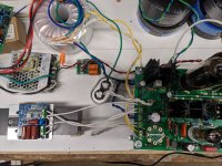
Hi Tom. I am using your maida regulator to replace the choke in one of George's UNSET beta boards. On my REW output I am seeing a spike in the 120Hz range that I am trying to reduce. Other than the 120Hz spike everything else seems to work fine with the regulator, V in is 465V and V out is set at 425V and remains stable. Attached is a pic of how I have it wired in. The off board cap in the pic is a 10uF on the output of the regulator and the green wire coming off it is the connection to ground. Do you see anything in my setup with the regulator that would be a likely cause of the hum?
Attachments
Thank you Tom for sharing ideas about Maida regulator.
What would be the latest scheme do use for DIY? I see some have made their own modifications.
Some use transistor ZTX450. What is the function of this transistor and how it affects this regulator?
I would be very happy if someone could share their final working controlled stable HV regulator with low noise and very low PSRR in audible Hz range.")
What would be the latest scheme do use for DIY? I see some have made their own modifications.
Some use transistor ZTX450. What is the function of this transistor and how it affects this regulator?
I would be very happy if someone could share their final working controlled stable HV regulator with low noise and very low PSRR in audible Hz range.
- Home
- Vendor's Bazaar
- 21st Century Maida Regulator