So, back to the question of industrial control transformers.
I see where there are several 250vA with 600v primary and 120/240v secondary.
If i get two of them, and backfeed them with 120v across the 240v winding, that should give me near 300v on the other side, and then i can hook them up in series, and build two high voltage supplies - one for the driver boards, one for the output tubes.
Right?
That would be about $40 shipped for the HV power iron, and then I'd get a couple anteks for heater power and bias power.
Keep in mind that the voltage ratios on a typical transformer include a hidden 5% to 10% boost in the forward direction to make up for copper losses under full load. So running one backwards will give you a 5% to 10% reduced voltage with no load, and 10% to 20% reduced V under full load. One can also play with inductor input DC filters if you want VDC more like 0.9X of the VAC (instead of approx. 1.3X with cap input) And then one can also play with a small cap before the LC filter to get something in between 0.9X and 1.3X of the VAC.
Last edited:
That's actually fine. 270vac would be more manageable than 300vac. 240vac wouldn't be bad either.
I would of course want to test the psu with a dummy load (buncha lightbulbs?) to get a good idea of what the actual voltages are, so that i can build the amp accordingly.
My brain is cramping over whether i would still get enough current out of the pair for 125wpc. Maybe i need more coffee.
I would of course want to test the psu with a dummy load (buncha lightbulbs?) to get a good idea of what the actual voltages are, so that i can build the amp accordingly.
My brain is cramping over whether i would still get enough current out of the pair for 125wpc. Maybe i need more coffee.
Well, the xfmr is still rated for the same RMS current as before, whichever way you use it. But cap input DC filters make for spikey current draw, which reduces the xfmr current rating considerably (high I2R losses). I have to look up the reduction factors every time, depends on full wave center tapped, or full wave bridge configuration too. The bridge is better.
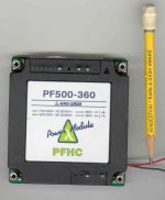
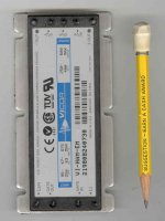
One can also get those PF (power factor) controllers to do the AC to DC task, regulated DC output. (check Ebay for cheap Lambda PF500-360, 500W 360VDC) (Vicor makes some too, I think maybe lower VDC too, maybe 270 VDC?) They are all non-isolating boost regulators, so still need the xfmr. for isolation. They typically run from 120 VAC or 240 VAC. They draw sinusoidal current off the power line. But need some shielding and caps. You may still want a DC amplified capacitor regulator (a Mosfet with RC Vref) after them to make for rock bottom DC supply impedance.
Lambda and Vicor PF module pics
(I think the Vicor one is for a post PF controller, electronic, DC filter, I couldn't find the PF part off hand here, but it's the same size)
Attachments
Last edited:
Oh,
that IS the Vicor PF controller module pictured above right, the active DC filter module is half as long (confusingly also called HAM for harmonic attenuator module). Looks like it does anywhere from 250VDC to 400VDC regulated output. (an external adjust pot.) These PF controllers were from around 10 or 15 years ago, so probably newer models are out by now. But these are the ones likely to be found on Ebay for cheap.
that IS the Vicor PF controller module pictured above right, the active DC filter module is half as long (confusingly also called HAM for harmonic attenuator module). Looks like it does anywhere from 250VDC to 400VDC regulated output. (an external adjust pot.) These PF controllers were from around 10 or 15 years ago, so probably newer models are out by now. But these are the ones likely to be found on Ebay for cheap.
Last edited:
Well I ordered a pair of Hammond PH250AJ industrial control transformers off ebay. $38 shipped for the pair.
I am thinking about a deep case with the power supply on the bottom under a shield, hard-wired umbilicals to the top plate. Just tubes and output iron on top.
Leaning toward just picking up a 100va 6.3v antek for heater current and using the tubes that are tried and true in the 125wpc red board builds.
I'm on page 125 of the redboard thread.
Yes, I have used 24 volt Mean Well switchers from Jameco to run 26LW6's and I got a pair of 36 volt Mean Wells for 36LW6's and 35LR6's...
How do the Mean Well switchers behave at start-up time, while they're overloaded by cold heaters? Or did you go so big on the switchers that overload doesn't occur?
I wonder if you can soft start with MOVs.
The MOV is a transient suppressor.
There are Inrush Current Limiters (that look like MOV's) made to slow the start up of many power supplies, including an SMPS if that was part of the initial design.
We use these in my Tubelab amps to slow start conventional power supplies. They usually will not help soft start an SMPS unless it was designed for that purpose. An SMPS will not start up unless it sees an input voltage above its minimum spec. It then starts rather quickly, providing full output voltage within a few mS. If the SMPS sees an overcurrent situation, it shuts down. Some try to restart, some don't. Some are more touchy about how much overcurrent they tolerate than others.
Yeah, after i submitted that i doubted the idea. In big disk arrays they use staging, spinning up a few at a time instead of all at once.
Just getting a switcher rated 2x the heater needs is way easier than building a circuit to power up heaters one at a time.
.:Sent by pneumatic tubes
Just getting a switcher rated 2x the heater needs is way easier than building a circuit to power up heaters one at a time.
.:Sent by pneumatic tubes
Could tho. 555 timer with a relay. Cascade 'em. Have the final one switch on B+ for you.
Not "hard" but over-engineered
Indeed, you can buy pre-built delayed start (or delayed stop) relay modules very cheap:
New 12V Delay Timer Monostable Switch Relay Module NE555 Car Oscillator-in Relays from Electrical Equipment & Supplies on Aliexpress.com | Alibaba Group
About a buck each. Relays rated at 10A 30VDC
If your heaters are something other than 12v, you'll need a bunch of 7812 regulators. or the 5v version of those modules, and 7805's.
Could be cobbled up in a couple hours (after waiting 2-5 weeks for delivery from china). The staging may only need to be a half second or so, which would allow you to do some snazzy effects on an amp with a lot of tubes, of you wanted to.
Be careful with multiple units of 1 from a single seller on aliexpress tho -- it's probably due to vagaries of what size of package qualifies for what rate, but sometimes "free shipping" jumps to "ok now you are paying for rush EMS" at some point.
Usually you can find a listing for a larger quantity of something.
Keep in mind that the voltage ratios on a typical transformer include a hidden 5% to 10% boost in the forward direction to make up for copper losses under full load. So running one backwards will give you a 5% to 10% reduced voltage with no load, and 10% to 20% reduced V under full load. One can also play with inductor input DC filters if you want VDC more like 0.9X of the VAC (instead of approx. 1.3X with cap input) And then one can also play with a small cap before the LC filter to get something in between 0.9X and 1.3X of the VAC.
With 120v(ish) across the winding marked for 240v, and a string of 3 60w light bulbs across the primary marked for 600v, I'm seeing 262vac.
Seems like it should work fine. I'll have to play with RC filter values in PSUD2 to land at the right numbers.
- Status
- This old topic is closed. If you want to reopen this topic, contact a moderator using the "Report Post" button.
- Home
- Amplifiers
- Tubes / Valves
- 21LG6/A P-P for 50+ watts?