
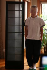
HahahahaYes, that's one solution, but I want to see trough my speaker, it's almost all about the looks
I can understand the see trough aspect, but it also means that you have to choose between good sound and good looks....but I agree that see trough is very important, look here at my speaker!
Picasa Web Albums - Jonas - Drop Box
It has a very low resonance peak in the audible spectrum. I suspect that this fact is due to that the weight of the stators dampens the 15-20 hz (with dismounted stators) resonance.
Another way is to place a 5 to 10 ohm resistor paralleled with a 50 uF audio capacitor in series with drive transformer input, to form a high pass filter. It also have the benefit of putting less low frequency energi strain into the transformer. Do some experiments with different values.
JarreYuri, what's so funny?
It was about "It's all about the looks"
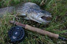
Finally, the weather was bad enough for to do some measurements (not to go to fishing trouts )
But first, the high voltage, I don't know... A little bit lover than the sparks The hardware is from ER-Audio.
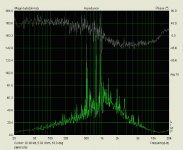
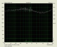
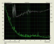
There's quite a lot noise in my impedance measurements, but I guess the message is coming trough anyhow. 1st one is plain panel, 2nd with 1 ohm series and 2.8 Ohm parallel "RS".
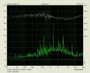
Now I have 1.8 Ohm parallel resistor and there's still bit of a bump in the impedance curve (I'm pretty sure that if I go to 0 Ohms it will level out ) as you can see from the 3rd picture and it's in a nicer scale too...
Now I have to try out that software and see if I can manage to create a circuit that is behaving like the measured one. Or are the measurements way of what they should be?!?
)But first, the high voltage, I don't know... A little bit lover than the sparks
The hardware is from ER-Audio.There's quite a lot noise in my impedance measurements, but I guess the message is coming trough anyhow. 1st one is plain panel, 2nd with 1 ohm series and 2.8 Ohm parallel "RS".
Now I have 1.8 Ohm parallel resistor and there's still bit of a bump in the impedance curve (I'm pretty sure that if I go to 0 Ohms it will level out
) as you can see from the 3rd picture and it's in a nicer scale too...Now I have to try out that software and see if I can manage to create a circuit that is behaving like the measured one. Or are the measurements way of what they should be?!?
Attachments
Last edited:
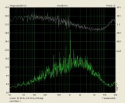
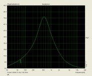
LSP-CAD is working fine Made an another impedance measurement to get the "complex impedance" txt-file exported for the LSP-CAD.
Something funny is going on with my measurements, much lower impedance bump this time. Have to make a prober circuit to measure the thing (now there's just a awful pile of leads everywhere and I'm using headphone amp of my stereos on top of that).
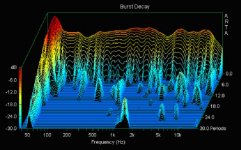
A couple of new charts below anyway, 1st panel only 2nd with RS+200uF series capacitor.
Been playing with the LSP-CAD and trying to get the notch filter values, it seems that I will end up with a huge inductor for the RLC-circuit. 50mH to get it down to 50Hz. Too big, but I still have hope, I'm probably doing something wrong here.
Made an another impedance measurement to get the "complex impedance" txt-file exported for the LSP-CAD.Something funny is going on with my measurements, much lower impedance bump this time. Have to make a prober circuit to measure the thing (now there's just a awful pile of leads everywhere and I'm using headphone amp of my stereos on top of that).
A couple of new charts below anyway, 1st panel only 2nd with RS+200uF series capacitor.
Been playing with the LSP-CAD and trying to get the notch filter values, it seems that I will end up with a huge inductor for the RLC-circuit. 50mH to get it down to 50Hz. Too big, but I still have hope, I'm probably doing something wrong here.
Attachments
Last edited:
I got the final kick to put my brewing kit (3 tier) in brewing order... Puck the impedance
Very pleased with the speakers and win amp equalising + subwoofer. Will go trough my music (>800 CDs) and have a few good beers to help me decide what to do next. I really like the lower bass, would hate to cut it out. -> dipole bass...
An example, The Gardigan "Grand Turismo", bass is amazing, every other systems that I have had blurred all the stuff, now it's crystal clear.
Back to the beer and music (and fishing tomorrow)
Very pleased with the speakers and win amp equalising + subwoofer. Will go trough my music (>800 CDs) and have a few good beers to help me decide what to do next. I really like the lower bass, would hate to cut it out. -> dipole bass...
An example, The Gardigan "Grand Turismo", bass is amazing, every other systems that I have had blurred all the stuff, now it's crystal clear.
Back to the beer and music (and fishing tomorrow
)
Last edited:
OK, about a 40 trout and a 100 litres of the homebrew later I got my self to build the speakers to the "ready stage". Might still but a wooden strip on the side of the frame to cover the gap between the mdf-sheets.
There was some issues with the 1st setup, the mylar and spacers separated after one of the speaker fell down (too much homebrew...). Also there was a lot of HV-leaking going on because of the poor insulating of the stators. The glue that I used wasn't that good either, so a redo was called. A few more layers of the varnish and this time the HV-testing BEFORE the build
I used a double sided tape this time to attach the mylar to the spacers. A one good thing about the the tape is that I was able to insulate the edges of the perforated sheets with the tape ("rolled over the other side"). There was leaks at the sharp edges that I wasn't able to fix properly with the varnish.
Alignment of the holes was pain though, but after I got idea of using matches to separate the sides while I got the holes in line everything went OK. How are you other tape users doing the alignment? Pretty painful to do at least with out helping hands...
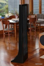
Will do some measurements next time I got the motivation...but they sound pretty good and even the sound level of the pair is identical (judging by the stereo image). That wasn't the case with the previous build...
->Wachara C
The sub ( Image12 ) and just the series capacitor for the ESL's. Not ideal, should really have two subs, dipoles...
I will start a new project after the trout fishing season is over, wire stators and a bigger size.
There was some issues with the 1st setup, the mylar and spacers separated after one of the speaker fell down (too much homebrew...). Also there was a lot of HV-leaking going on because of the poor insulating of the stators. The glue that I used wasn't that good either, so a redo was called. A few more layers of the varnish and this time the HV-testing BEFORE the build
I used a double sided tape this time to attach the mylar to the spacers. A one good thing about the the tape is that I was able to insulate the edges of the perforated sheets with the tape ("rolled over the other side"). There was leaks at the sharp edges that I wasn't able to fix properly with the varnish.
Alignment of the holes was pain though, but after I got idea of using matches to separate the sides while I got the holes in line everything went OK. How are you other tape users doing the alignment? Pretty painful to do at least with out helping hands...
Will do some measurements next time I got the motivation...but they sound pretty good and even the sound level of the pair is identical (judging by the stereo image). That wasn't the case with the previous build...
->Wachara C
The sub ( Image12 ) and just the series capacitor for the ESL's. Not ideal, should really have two subs, dipoles...
I will start a new project after the trout fishing season is over, wire stators and a bigger size.
Attachments
Hi,
... You are going to trade one squaller against the other? *lol*
Naaa, just kiddin´
jauu
Calvin
????????????
Urban Dictionary: Squaller
Vmk, very nice speakers! Keep on building!
Last edited:
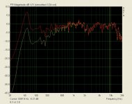
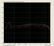
Had to add more wire to the transformer primaries. Starting point was 5.7VAC when the transformers were in 230VAC (2*toroidals/ESL). Added a 15 rounds to each transformer to reduce the step up ratio. Still enough of the squall to my ears even with a low power amp. The red curve in the attached picture is the after situation (both measurements with a 1 Ohm series resistor).
My Mylar is not as thigh as I was planning it to be and the resonance is very low. I guess that the tape that I was using to fix the mylar to spacers gave away. Next time I know better.
Still busy with the fishing (as you can see) so I just "have to" live with this set up for a while. The speakers sound really nice... except the lows, need something to between 50-200Hz, now the transition from ESL's to the sub is awful.
My Mylar is not as thigh as I was planning it to be and the resonance is very low. I guess that the tape that I was using to fix the mylar to spacers gave away. Next time I know better.
Still busy with the fishing (as you can see
) so I just "have to" live with this set up for a while. The speakers sound really nice... except the lows, need something to between 50-200Hz, now the transition from ESL's to the sub is awful.Attachments
Last edited:
- Status
- This old topic is closed. If you want to reopen this topic, contact a moderator using the "Report Post" button.
- Home
- Loudspeakers
- Planars & Exotics
- 2-way esl