This is all deeply interesting, Doug. There's nothing like actually doing it. 
I'm reminding myself that this is a 4 ohm 0.8mH polypropylene woofer, with a Vifa XT25 tweeter known for its low resistance of Re=3 ohms and no ferrofluid which makes for a a big response peak at Fs which needs consideration.
I'd guess your amplifier is losing it a bit with the 4.7uF capacitor. Probably the bass and tweeter are interacting given the low impedance. The hidden peak of the tweeter Fs resonance is always going to be sensitive too, and Vifas are known to sound rough if it gets overdriven, which you are doing with low order and Q filters here. 3.3uF and 4uF always seem to be the magic values at 8 ohms nominal.
Your crossover layout may be playing a part too. When you have wires far apart, you are opening up to inductance, particularly at very high frequencies. Coil and capacitor placement and can matter too, as Troels explains:
Placement of coils in crossover networks
But if it works, it works. BTW, how is the bass performance. Are these best near a wall or away from one?
The speakers are 30cm away from a cinder block wall; bass is really nice, sounds like there is a 8" subwoofer in the room.
I'm using a Rotel 980BX (120w per channel) to run them, there is a active xo set at 32hz. [subwoofer amp is off]
I will consider using the sand ploy again; this sand is synthetic, the granules are large for sand; still have 10 gallons of the stuff.
I'm using a Rotel 980BX (120w per channel) to run them, there is a active xo set at 32hz. [subwoofer amp is off]
I will consider using the sand ploy again; this sand is synthetic, the granules are large for sand; still have 10 gallons of the stuff.
Ah, yes. Built like tanks those Rotel power amps. Always wanted a second RB971 power amp for the bridged mode thing! I think I got up to five lovely black units stacked at one stage. Wondered if the bottom one was going to get crushed. The DAC was awesome.
Alas my ex has possession of my high end Rotel stack some of which is in this picture. Too nice to ask for it back. It's doing her TV sound.
Much more modest these days. But I expect I will get something new soon.
Alas my ex has possession of my high end Rotel stack some of which is in this picture. Too nice to ask for it back. It's doing her TV sound.
An externally hosted image should be here but it was not working when we last tested it.
Much more modest these days. But I expect I will get something new soon.
ODougbo said:Very surprised there was a huge difference with a small change.
This can happen when you're getting close somewhere. The changes get smaller and smaller, more specific and easier to make something else worse at the same time.
I couldn't hear any difference with the woofer cap; I added to it a couple times. What should that do, increase the slope/midrange?
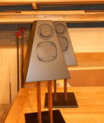
The triangle speakers are next, have duplicate parts - 3.9uf tweeter cap. Funny but true, tiny little thing(s) (poly) think I should order some nicer ones?
The triangle speakers are next, have duplicate parts - 3.9uf tweeter cap. Funny but true, tiny little thing(s) (poly) think I should order some nicer ones?
Attachments
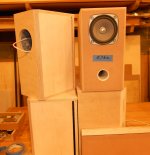
I guess I could find one Allen. I did work on the black pair yesterday, while listening to the sand filled ones (which I'm loving).
I took out the cut foam out and replaced it with 3.5oz typ. damping/stuffing material. This is the same as the oak/sand pair.
I do wish I could get the black pair to sound as good. What would I listen for? The panels are 1" thick, lead-lined and very solid.
The oak pair is 3/4" mdf with 1/4" sand (set in glue).
Both set of BR boxes are same volume and ported with 5" x 1-1/2" pvc.
I can go over a panel and find the pattern of the resonance. For example that a panel vibrates at 1/4 and 3/4 the way across, all the way up and down it. Based on this and on what I can hear I can decide whether to brace more or damp more, and where. It helps me decide whether a panel resonance is a possible source of a problem I can hear, or weaknesses in a front baffle with large cutouts.
It isn't possible to hear much, per se. You can tell the broad range of frequency but it's fairly easy to tell where a panel is and isn't vibrating. You could always try using a glass for this.
By the way, a panel resonance can exist even if you have very large amounts of stuffing in your boxes. They can start by direct contact with the driver.
Attachments
Last edited:
As it looks like you can't send attachments over a PN, I am dropping this here.
Modeled the FF125K at 9L with two different alignments. Note that when you actually measure the 72Hz tuning it is better behaved with an F3 at about 75 Hz. So, with a sub and a tweeter, has good promise.
Modeled the FF125K at 9L with two different alignments. Note that when you actually measure the 72Hz tuning it is better behaved with an F3 at about 75 Hz. So, with a sub and a tweeter, has good promise.
Attachments
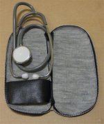
Nice stuff to play the doctor
Perhaps a microphone, a sound card and a sound analyser could do the tricks ?
When I make my rig portable, I'll take it over.
I guess I should have mentioned, looking for the best low end output.
I'm assuming the white is the better curve.
For anyone interested...I'm putting new sides on Fonken, don't know where to tune it. Some where around 60hz - 70hz. 72?
The box with blue tape is the Fostex box as per in-the-box-plans.
I'm assuming the white is the better curve.
For anyone interested...I'm putting new sides on Fonken, don't know where to tune it. Some where around 60hz - 70hz. 72?
The box with blue tape is the Fostex box as per in-the-box-plans.
Attachments
Madisound Speaker Store
They list the 125wk as 9L 57hz, I must have done something right (didn't know that when checking)
They list the 125wk as 9L 57hz, I must have done something right (didn't know that when checking)
The yellow will give far more perception of bass. The white is the Fostex value. You just can't make something do what it can't do. The bright green is -3 dB. As you can see, they both fall off at about 200 Hz. I would go for the 70 Hz range. The good news in measured, the yellow is actually a little better than that. Sim is never quite correct. I expect the white is better too. Waiting for glue to dry, on my X45 ( successor to the SR71) so I'll try and get some measurements of the striped cabinets.
Ran it in WinISD and roll off starts at 72hz, -3 is 58.5hz.
Lines are very straight - tuning, 63hz.
(*&^%$ never could get screen shot to work.
I cheat. I have an old program called PrintKey 2000. Fantastic program.
Our numbers don't seem to match. We should compare parameters. The way I type, who knows!
Shooting in the dark
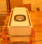
Tvgeek, maybe you could measure the bass response with the different number of strips, e.g.:
No strips - 82hz
2 strips - 75hz
4 strips - 70hz
6 strips - 61hz
The box/woofer did seem (to me) that it was just working too hard with all 6 strips in.
Tvgeek, maybe you could measure the bass response with the different number of strips, e.g.:
No strips - 82hz
2 strips - 75hz
4 strips - 70hz
6 strips - 61hz
The box/woofer did seem (to me) that it was just working too hard with all 6 strips in.
Attachments
Last edited:
- Status
- This old topic is closed. If you want to reopen this topic, contact a moderator using the "Report Post" button.
- Home
- Loudspeakers
- Multi-Way
- 2 way crossover design help