What I'm wondering about is if the 20uF for +B1 holds enough energy...
I have my doubts too. I'd want at least 47 muF. in those positions. I'd also increase PSU cap. 1 to 15 muF.
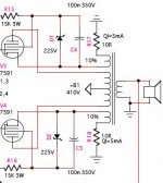
+B2 Ripple prediction is 100mV at quiescent, 200mV at max output current. There is only a small cap in the filter at present.
PSU caps. 5 and 7 need to be larger, perhaps as much as 33 muF. A low ripple voltage seems indicated in the Class "A" small signal circuitry's supply. Also, sufficient energy storage is needed to survive peaks when the check valve diodes "close".
I compute that the decoupling resistors should be 470 Ohms, not 1 KOhm. Allowance has to be made for the 1.2 V. forward drop of a UF4007.
Eli,
I'll follow all those recommendations, but I don't understand:
I'll follow all those recommendations, but I don't understand:
Also, sufficient energy storage is needed to survive peaks when the check valve diodes "close".
John,
The UF4007s in the decoupling networks allow energy in, but don't allow it to escape (check valve). Should the diodes get reverse biased in a transient situation, the caps. in the decoupling networks have store enough energy to keep the Class "A" driver circuitry running well, until the transient has passed.
Let's see. 410 - 1.2 = 408.8 So, 8.8 V. needs to be dropped in the decoupling resistance. Ohm's Law says a 518 Ohm resistor is "perfect" for a 17 mA. draw. Appropriately rated 500 Ohm inductive wirewound parts combined with 18 Ohm parts of your choice look FINE to me. 470 Ohms is a "close" common value, but we can do BETTER.
John,
The inductive 'T7 load resistors provide some phase compensation without introducing caps. in the NFB loop. The exact amount of compensation needed depends on the character of the O/P trafos used. If, during the debugging stage, you determine additional phase compensation is in order, add RF chokes in series with the 'T7 load resistors. You will get additional HF peaking in the splitter.
FWIW, I think you will be OK if there is a SLIGHT excess of HF peaking, as the loop NFB will flatten things out. I'm more concerned about a large error correction signal trying to deal with HF roll off.
All,
Anyone who has a line stage with gain can build a variant of this concept that's not as sensitive. Simply use a 6J6 instead of a 12AT7 in the splitter/driver role. The 6J6's mu is approx. 0.5 that of the 12AT7.
If ever there was a tube "born" to be used as a differential phase splitter, it's the 6J6.")
Anyone who has a line stage with gain can build a variant of this concept that's not as sensitive. Simply use a 6J6 instead of a 12AT7 in the splitter/driver role. The 6J6's mu is approx. 0.5 that of the 12AT7.
If ever there was a tube "born" to be used as a differential phase splitter, it's the 6J6.
dhaen said:Looking for an output transformer supplier, preferably European. Must be willing to supply just 1 pair, custom wound for a reasonable price.
Currently looking at Sowter, VVT, AE-Europe.
Any further recommendations are most welcome.
John,
I'll toss Stevens and Billington (UK) and Bartolucci (Italy) out. However I suspect you know far more about the European "scene" than I ever will.
FWIW, I lean towards Sowter. I've exchanged EMail messages with Brian S. several times and I always found him to be HELPFUL. The lamination stack is certainly not a problem. Use the same stack as goes into PP EL34 O/P trafos. Heck, Mr. Sowter will add the new design to his already large database.
Eli,
AFAIK S&B only make small signal permalloy types. Bartolucci have quoted me before and I found them the most expensive.
Yes, Brian Sowter is the most helpful I've come across, and his transformers are marvelous. He even has one that is close, U066 but the price is still a bit high for me at (UKP)£108.16 each + VAT. However, custom winds cost the same.
If I can't find a good price elsewhere, I will go with Sowter, probably the next size up though.
John,
The U066 uses the "L" lam. stack. Sowter shows the U057 EL34 trafo on the "M" stack, but its spec's look quite marginal to me. The UA21 is also an EL34 trafo with excellent spec's on the "N" lam. stack. Perhaps Brain S. can adjust the UA21 to match with this project's needs. I am WELL aware of the financial implications of the "N" lam. stack.
If you go with Sowter's "M" lam. stack, move the I/P high pass filter turnover freq. up to approx. 24 Hz. O/P trafo core saturation due to a large low freq. NFB error correction signal must be prevented.
Eli,
I think what you're suggesting is I pay much more - ouch.
Bas,
2 * 10% isolated tertiary windings are ideal.
EI, -3dB @10Hz.
Secondary impedance 8 ohms.
Primary impedance - let's say 6K -, still undecided, as I'm not clear of the distortion implications with pentode mode. I can't seem to find any rules.
Hey John,
I think I can do what you want. Probably cost about ~$150 each. I have been working on just such an item, but I had not planned on TWO seperate windings.
Keep in mind that if you take a 6k a-a, and att 10% at the cathode, you wind up with ~6k8 of "a-a" load ( 1.1^2 * 6k).
How about 6k4 with 12.5% paired tertiary windings. I think it will fit in a 1.375 scrappless lam. Make its stack at least 2" thick.
Drop me an email if you're interested.
cheers,
Douglas
Bandersnatch said:
Keep in mind that if you take a 6k a-a, and attach 10% at the cathode, you wind up with ~6k8 of "a-a" load ( 1.1^2 * 6k).
ooops, math error, it would be a 7k2 load.
cheers,
Douglas
Hey-Hey!!!,
The cathode windings are traditionally one CT coil. It looks like you have an interesting scheme to maintain pentode operation through the Zener and 15k dropping R.
I have a few questions about your provisions for dealing with high g2 current, but they don't involve the OPTx. That is fairly straightforward. You'll get a 6k4 and 12.5% cathode coils. Might be able to play with the ratios a little bit to head for 6k and 10%.
Keeping the two cathode windings seperate is no biggie, just requires a bit more colours for labeling it. It sounded like you wanted four 10% sections...this is a bit easier.
cheers,
Douglas
Douglas,
Yes, there could be dropout. I normally run zeners just on the knee, but the g2 current and +B may vary with signal. An issue bought up in another thread is that of noise in HV zeners. I think both issues can be resolved with a sutably large value cap in parallel.
I have a few questions about your provisions for dealing with high g2 current,
Yes, there could be dropout. I normally run zeners just on the knee, but the g2 current and +B may vary with signal. An issue bought up in another thread is that of noise in HV zeners. I think both issues can be resolved with a sutably large value cap in parallel.
There is another possibility to keep the g2 at a speerate voltage and even with the cathode: another winding for the g2, equal to the cathode winding.
slightly more complex ov course...
I've seen g2 regulator drop out on an RCA amp converted from 6146 to 6550. The 0C3's were swapped for 0D3's and at even partial boogie, the single g2 would consume all the available current and the VR tubes would go out.
I think it's neat how you keep the CFB coil operating at constant current( drop-out, and plate contributions excepted ). What comes through the resistor either comes along through the g2, or gets through the shunt reg...neat. When it drops out, I wonder how it will sound.
I am not a fan of AB1 amps, so I'd suggest a single CFB winding, and tap at the same point on the anode winding so you'd have the opposite g2 attached there. Full pentode, and Class A. Or was it you concerned with heat?
cheers,
Douglas
- Status
- This old topic is closed. If you want to reopen this topic, contact a moderator using the "Report Post" button.
- Home
- Amplifiers
- Tubes / Valves
- "2 Stage" PP 7591 Amp