I am using Xover 3 Pro for a project
When I use a 2 nd order LR filter I get a sharp spike pass the the crossover point than the 12 db
I am using Silver Flute W14RC25-04 ohm 5-1/2" Wool Cone from Madisound in parallel Xovered at 2750 or 3000
When I use a 2 nd order LR filter I get a sharp spike pass the the crossover point than the 12 db
I am using Silver Flute W14RC25-04 ohm 5-1/2" Wool Cone from Madisound in parallel Xovered at 2750 or 3000
But The xover is suppose created a drop not a rise
There should be no sharp spike apparently one of the speaker specs having to due with the capacitance of the coil is an issue. A LR 2nd order xover should be -12 at the xover point and it should be about -20 db at at 5 khz and if I use a 1st order Xover the spike goes away which has a 3 db drop at the crossover point.
And the spike is a very sharp spike no way is it similar to the rise characteristics of the manufacturer's specs
I am using Xover 3 Pro for a project
When I use a 2 nd order LR filter I get a sharp spike pass the the crossover point than the 12 db
I am using Silver Flute W14RC25-04 ohm 5-1/2" Wool Cone from Madisound in parallel Xovered at 2750 or 3000
Hi mcmahon,
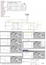
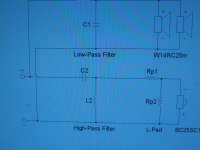
My 2 cents of XO hints: See the picture.
b
Attachments
Is the spike you are seeing present in real measurements of the speakers using the built crossover or only in the simulation?
I've noticed in speaker workshop large peaks in response (also with second order electrical crossovers) at places where it shouldn't happen, Note that this has been when modeling the crossover for a single driver, nothing to do with summing with the other driver. I've put it down to the simulator showing resonances between the cap and the coil which shows up as a peak in the response. I haven't actually built one of the circuits to see what happens in real life, but my suspicion is that it won't happen... I'm basing this purely on the fact that they are passive components, and shouldn't be causing peaks in response of a driver that are not there without the crossover.
Tony.
to small to make it out
click on the four arrow cluster in the bottom left corner. It will expand further.
That was what I was thinking since it is passing through
Since the electrical energy is being passed to ground before reaching the speaker, I will build and see what happens though, but it make it harder to get a good starting point in Xover pro. And the part of the resonance is do to being in a box, whereas I will be using a hybrid design to fight the box effect.
Since the electrical energy is being passed to ground before reaching the speaker, I will build and see what happens though, but it make it harder to get a good starting point in Xover pro. And the part of the resonance is do to being in a box, whereas I will be using a hybrid design to fight the box effect.
Try modelling with a small resistance in series with the cap in the low pass section (try values between 0.1 and 1). This will probably get rid of the resonant peak if that is what it is. when it comes to the real implementation you can try with and without the resistor.
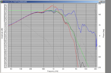
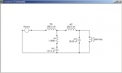
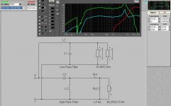
edit: I've added a graph, blue is the actual woofer response, red is 4th order crossover without a resistor in series with the first cap. black is response with a one ohm resistor in series with the first cap, yellow is the 4th order LR target response. Xover with resistor is the second attachment. I'm assuming that this is the type of behaviour you are seeing?
Tony.
Attachments
Last edited:
I don't know who's designing the xover here, but I did this RLC for this nasty woofer that seems to work (@1Kz) in my/it's case. If the frequency (like in this/your case) is after the xover point I would revise it for a different/higher order or change driver. Design with the help of the drivers, not against it. It's more difficult.
http://www.diyaudio.com/forums/multi-way/164418-need-some-help-some-bass.html#post2142087
http://www.diyaudio.com/forums/multi-way/164418-need-some-help-some-bass.html#post2142087
There are many ways to skin a cat
Last edited:
Hi Inductor, If I'm interpreting properly the OP is designing a crossover, and his simulation results seemed odd, in that there is a peak in response which doesn't make sense, because the peak isn't there in the original driver response.
What I have posted is my own crossover simulation (based on actual measured raw driver response). I believe the peak (in red) is an artifact of the simulation software and would not be present in an actual implementation of this crossover (I haven't yet got the coils to make it). However if there is a resonance there, whilst I don't think it will cause the predicted response peak, may affect the sound, and the addition of the 1 ohm resistor should damp it out.
Tony.
It looks to me like the spike is caused by not having a zobel network i.e R-C across the driver. Bjorno's analysis partially shows the effect of this.
My blog:
Consort3′s Blog
My blog:
Consort3′s Blog
There should be no sharp spike apparently one of the speaker specs having to due with the capacitance of the coil is an issue. A LR 2nd order xover should be -12 at the xover point and it should be about -20 db at at 5 khz and if I use a 1st order Xover the spike goes away which has a 3 db drop at the crossover point.
And the spike is a very sharp spike no way is it similar to the rise characteristics of the manufacturer's specs
Hi Mcmahon48 I just realised there is a mistake in your post here. The response should be down 6db at the crossover frequency not 12db for a 2nd order LR crossover.
If your crossover freq is 2.75KHz then it will only be down 18db at 5.5Khz.
I think it would help if you posted a picture of the response problem you are encountering, as I think I am interpreting what you are seeing differently to everyone else
") It should clear things up one way or the other!
It should clear things up one way or the other!Tony.
Hi McMahon48, it looks like the spike is close to 15db around 3.5K which certainly doesn't look anything like the response curve linked to in the first post. which is a broad 5db hump between about 5 and 7K (starting at 4K and finishing at 9K)
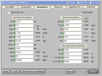
Could you post the frd file that you are using for the woofer and also your crossover component values? I'm interested to see if I get the same result in speaker workshop. I'm a bit intrigued by the same sort of behaviour with my own crossover modeling, both speaker workshop and Jeff Bagby's spreadsheet have given me similar results.
Also a much easier way to get screen shots is to use the <alt> <Prt Scr> key combo when you have the window you want to capture selected and then paste into a photo editing program and save.
Even better is the free screen grab program mwsnap available here I use it all the time. Start it up, press <ctrl> <shift> a and then drag the mouse over the thing you want a screen shot of and it grabs it. Then go to the menu and choose file save as and give it a name, I use png as it creates small files with no loss of resolution.
Tony.
I am using Xover 3 Pro for a project
When I use a 2 nd order LR filter I get a sharp spike pass the the crossover point than the 12 db
I am using Silver Flute W14RC25-04 ohm 5-1/2" Wool Cone from Madisound in parallel Xovered at 2750 or 3000
The first thing that sticks out to me is paralleling two 4Ω woofers gives you only 2Ω load!
I can only guess that you are using one 4Ω Peerless tweeter, but I would like to know the actual tweeter you are using and what the impedance is.
It just seems like creating a two Ohm load is out of the ordinary and then matching that to a tweeter of a different impedance is even more hairy.
On top of all of those issues you are using a software package that really doesn't have a very good reputation. So how do you know this spike is real?
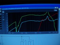
I know about the 2 ohms load and here is screen snap
I know about the 2 ohm load and that is why I am putting a 3.9 in series before the network which is included in the response output. Apparently I will need to use a first order network if the other modeling programs show the same result
+ 6db for dual speakers wired in parallel
Tweeter is http://www.madisound.com/store/product_info.php?products_id=8354
Attachments
Last edited:
I know about the 2 ohm load and that is why I am putting a 3.9 in series before the network which is included in the response output. Apparently I will need to use a first order network if the other modeling programs show the same result
+ 6db for dual speakers wired in parallel
Tweeter is Vifa BC25SC06-04 1" Textile Dome Tweeter from Madisound
You are going to dissipate a huge amount of power into a resistor?
About 50% of music power is below 500 Hz, so most of your audio power is going into a resistor and getting hot.
Your amp's damping factor will drop to zero. The extra heat will interfere with the driver operation as the internal temperature in the box will warm up the voice coil and the function of the crossover will be affected by the heat, too.
Maybe you have no better choices than what you are doing or another compelling reason to do things this way, but you are definitely swimming upstream.


- Status
- This old topic is closed. If you want to reopen this topic, contact a moderator using the "Report Post" button.
- Home
- Loudspeakers
- Multi-Way
- 2 nd order L/R cause spike?