Hello,
I want to build a 2.1 active system. It's all i think about
The crossover will be a 3-Way Linkwitz Rileytype, based on a Rod Elliott project (1 TL502 for input + 4x TL054) . The crossover outs will be buffered with 3 x OPA2064.
Crossover @ 94 Hz low pass goes into LM4766 parallel for subwoofer, 94-3400 Hz band pass goes into stereo LM4766, likewise for 3400 Hz high pass goes into another LM4766.
All three amplifiers will be powered from a 230V/ 2 x18 V 250VA toroidal transformer, bridge rectified and filtered with 5 x 3300 uF(35V) and 100nF per V+ and V-.
Calculated with the Overture_Design_Guide15.xls. from National - the parallel configuration should have output of 54 W @ 25 V, and the stereo ones - 2 x 27 W.
The subwoofer will be a single JL Audio 12W1v4-4 4ohm 150W max RMS
in a sealed enclosure of 40.3 Litters or 1.425 cu. ft (in the schematic i made a mistake, i wrote 50L)
The mains will be 2 sealed boxes of 15-18 litters or 0.53 -0.636 cu. ft, the mid bass - Monacor SPH 170 and tweeter Monador DT-25N.
Will use only 1% resistors (5% ceramic caps for crossover). The hole system should be 45-20000 Hz _+ 3dB. Max power will be 103-106 SPL, i think this is more then enough for a bedroom.
I didn't build any LM4766 amplifiers and i don't know the value for the pins 6-11 to ground capacitor .... i found out the value for the mute resistor (12 - 12.5 Kohm).
I want to use this system mainly for enjoying music, maybe some monitoring/mixing. What to you think of this system?Any flaws? This should cost me 400-500 euro, which is max budget for me.
BR,
Claudiu
Hi,
I have only looked at the bass amplifier so far.
You have set the LF roll-off of the NFB loop too high for a bass only speaker. Do not use the NFB as a high pass protection for your bass cone. If you need extreme LF protection for your driver than add a separate active high pass filter of appropriate F & Q & poles
C1 & C2 should be 100uF to 220uF for a bass only speaker amplifier.
C1 & C2 should be matched to better than 1%.
R5 & R6 should be matched to better than 0.1%.
R3 & R4 should be matched to better than 0.1%.
R10 & R11 should be matched to better than 5%.
Both amplifiers have DC gain set to ~ X1 (+0dB).
Both amplifiers have no DC block at the input.
Both amplifiers have an interconnection that will pass input offset current between them and some to ground.
You will have output offset issues. This may blow up your parallel proposal.
You have no output offset trim.
As proposed the output offset of the amplifiers will be different and neither will be 0.0mVdc.
Remove the R0 (47k). insert trimming variable resistors after R1 & R2 to set the cold output offset to as near zero mVdc as possible. Do this for both channels independently. The idea is that they have matching zero output offset at switch on and do not blow themselves up at switch on.
Then you need to examine carefully how the output offset of each amplifier varies as the chips warm up.
National use DC servo feedback to correct for warm up output offset variations. You have none.
You have no RF filter at the input of either amplifier.
C6 can be anywhere between 22uF and 220uF for a shortish time delay off the unmute function.
R7 should pass >0.5mA over the full range of operating PSU voltages. See the graph in the datasheet. I suggest you aim for ~1mA
Do you want feedback on the Mid and Treble amplifiers?
Last edited:
Thx a lot for the replies, especially AndrewT for sharing so much!
It seems that it will be very difficult without DC servo. I still have the 25+_ Volts limitation so i can't go single chip.
What if i use the parallel design for LM4780 from NATIONAL data sheet?Will i still need a DC servo?
It seems that it will be very difficult without DC servo. I still have the 25+_ Volts limitation so i can't go single chip.
What if i use the parallel design for LM4780 from NATIONAL data sheet?Will i still need a DC servo?
Attachments
Hi,
adopting the National PA100 still seems to give problems.
Adopting a DC servo for each chipamp does not always avoid those same problems.
I am not at all sure why so many PA100 implementations go wrong, but I suspect one chip tries to do too much work at start up or soon after the chip starts warming up.
I never recommend beginners attempt any bpa, pa nor ba implementation.
Stay with simple single amplifiers and stick with AC coupled, not DC coupled nor mixed AC & DC coupled.
Ok, I will try to see if i can buy squezze in my budget an 160VA 2x25 toroidal, (+rectifier & caps) to make a separate power supply for a LM3886 sub amp.
I will research how to make the RF filtering for each amplifier. I thought that if i use the active crossover and the standard schematic for LM4766 i don't need to make other adjustments or additional components for input frequency filtering, but now i understand that using this would avoid oscillations.
I will try to redesign and then post all schematics, including the active crossover and the power supplies.
Thank you for all your input!
You can use an input capacitor of.. 1 uF , non electrolit type , that will block DC from Your actve xovers (original schematics), and as for RF filtering, a little ceramic cap from input to ground as close to the chip should prevent the amp from picking up radio signals. On some chipamps i was happy with 15 pf, on others i had to go all the way to 220 pf, on sub amps i allways used 330 pf.
I redesigned the crossover for lower noise and added a preamp with active volume. I now use NE5532 for op amps. The sub woofer amp is now designed as stereo with 8 ohm impedance sensitive driver - Peerless SLS 830669 - 12" - 106db @ 27W, will only buy 1 for starters.
I added caps for RF attenuation, minimally higher gain settings (27 db for sub and mids; 26db for tweeter), C1 and C2 in are now 220 for sub, 22 for mid and 1uF for tweeter. I would add 10-47 pF caps in parallel with the gain feed back resistors of the LM4766 if i sense HF oscillation ...
I did not "designed" the power supplies yet, but will use 500VA-600VA toroidal.
I uploaded all schematics. Would all this give a good result?
THX
Attachments
Discovering the thread of Carlos http://www.diyaudio.com/forums/chip-amps/43423-high-cap-unregulated-psu-chipamps-13.html
i will use his PSU design and lower the caps (100 uF) at LM4766 PSU pins.
i will use his PSU design and lower the caps (100 uF) at LM4766 PSU pins.
Hi,
how have you arrived at the coupling capacitor values?
They all seem too high. At some locations, lower would allow film coupling caps.
Many of the 5532 are feeding DC offset to the next in the chain.
You have DC blocking after the second in each chain. Adjust the output offset of the first 5532 in each pair by inserting a resistor from -IN to Audio Ground.
Why the double 5532 at the input?
A single inverting here would do the job and allow +0db, +xdbB and -ydB settings to be pluggable and/or switchable.
I would lower the RF filter frequency by increasing either or both of Rin & Cin.
The double op amp input is to have a high impedance input while having a lower signal resistor path for lower Johnson noise, i don't know any other alternative of having a quiet inverting input.
I don't think there will be a problem with having a small DC offset at the input of 1 in every 2 opamps, it should only influence the clipping voltage level, making it lower with only 10 mV. Max signal level should not exceed few volts while the clipping should be much higher than that?
The DC decoupling caps are high to prevent distortion of signal, especially in the lower frequency. I have read in a book (Small Signal Audio Design By: Douglas Self) that if you pass signal through an electrolytic cap, the signal will be less distorted (comparable with good film caps) if the cap is not charged; for each 220 cap there is an 22K ohm resistor that drains the caps of DC current. At least that is what i understand from that book.
Last edited:
A question regarding your wiring/construction plans: In an active system, isn't the amplification closely coupled to the speaker (physically, i.e. inside or near the respective speaker box)?
As of my understanding, what you're planning to do is a bi-/triamped system with an active crossover, not an active 2.1 system. I admit that this might be splitting hairs, though.
I think it's clever to have one LM4766 for the mids and another one for the highs, as this should minimize intermodulation between mid and high speakers and ease power supply requirements. But it arises the problem that both amps have to be connected to both speaker enclosures, so no 'active speaker' option here...
The reason why I'm asking is hum/noise management. It can be dealt with, but powering everything from the same supply makes enclosure layout and cabling tough...
Or you could go active, i.e. bundle mid and high into one LM4766 each and gain the option to separate left from right (with the added cost of separate supplies, though).
If you plan to integrate everything into the sub (or in a common enclosure), Speakon (4-pin) connectors and four-conductor cables are always handy.
2c,
Sebastian.
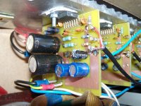
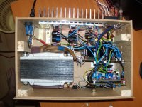
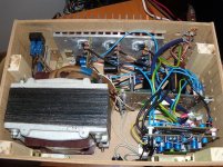
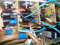
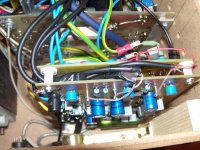
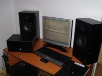
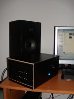
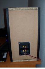
I have done it! Also finished the speakers. I still need to order the subwoofer and build the enclosure for it.
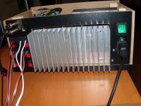
Its kinda messy inside with all that wiring, but it's all dead silent. I can't hear any hum or white noise unless i put my ear 10 cm close to the tweeter or up against the midwoofer. White noise is audible from half a meter away only if crank the volume more then 80%. Can't believe it's so quit with the transformer so close to the circuits. The box is made out of HDF and MDF board, no metal screening. Very happy how it turned out !!!
After i build the sub, i will add a larger heat sink for the rectifier bridges as they already get to 60 Celsius if i run more then 20 minutes at max volume.
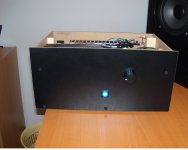
I admit the finishing doesn't look to good, but i am no carpenter, don't have the right tools nor the space ...
Very glad i started this project!
Its kinda messy inside with all that wiring, but it's all dead silent. I can't hear any hum or white noise unless i put my ear 10 cm close to the tweeter or up against the midwoofer. White noise is audible from half a meter away only if crank the volume more then 80%. Can't believe it's so quit with the transformer so close to the circuits. The box is made out of HDF and MDF board, no metal screening. Very happy how it turned out !!!
After i build the sub, i will add a larger heat sink for the rectifier bridges as they already get to 60 Celsius if i run more then 20 minutes at max volume.
I admit the finishing doesn't look to good, but i am no carpenter, don't have the right tools nor the space ...
Very glad i started this project!
Attachments
-
 DSCN8999.JPG174.8 KB · Views: 177
 -
 DSCN8997.JPG183.9 KB · Views: 171
 -
 DSCN8995.JPG172 KB · Views: 191
 -
 DSCN9001.JPG200.8 KB · Views: 163
 -
 DSCN9003.JPG180.7 KB · Views: 157
 -
 DSCN9004.JPG152.4 KB · Views: 89
 -
 DSCN9005.JPG106 KB · Views: 70
 -
 DSCN9018.JPG111 KB · Views: 72
 -
 DSCN9025.JPG117.9 KB · Views: 71
 -
 DSCN9027.JPG123.6 KB · Views: 66
Last edited:
- Status
- This old topic is closed. If you want to reopen this topic, contact a moderator using the "Report Post" button.
- Home
- Amplifiers
- Chip Amps
- 2.1 active system 3x LM4766