Hi diy's,
I'm looking for a way to make a 1Gohm or preferably higher value resistor (low wattage). Any of you have experience with this?
Might I take an older carbonblock resistor and scrap away the surplus or is there a more feasible way to do this? Please note that it is not an option to buy materials for this so need be surplus, second hand, things for waste, or the like ...
Suggestions are appreciated,
Greetings,
Jesper
P.S.: It need not be more precise than 10-15% and temperature stability is less important.
Last edited:
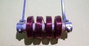
You can make a very high gigohm resistor with a suitable ceramic form and India ink. I once made one from a choke that I unwound like to one below. A single straight line or multiple lines will do it. The more ink you use, the lower the resistance. But I'm talking very high resistance, and you'll probably need a good megohmmeter to measure it.
Attachments
You need to specify required accuracy, power rating and expected voltage before anyone can give a serious response.
10 x 100M 5% 1/2W resistors in series is trivial to do, will give you a 1KV rating easily. But it needs space and the bandwidth will be c**p.
If it is in a feedback loop, a much lower value "T" network will often serve.
What do you need?
10 x 100M 5% 1/2W resistors in series is trivial to do, will give you a 1KV rating easily. But it needs space and the bandwidth will be c**p.
If it is in a feedback loop, a much lower value "T" network will often serve.
What do you need?
You need to specify required accuracy, power rating and expected voltage before anyone can give a serious response.
10 x 100M 5% 1/2W resistors in series is trivial to do, will give you a 1KV rating easily. But it needs space and the bandwidth will be c**p.
If it is in a feedback loop, a much lower value "T" network will often serve.
What do you need?
Hi - thanks for your tips.
Bandwidth is very low (<10 Hz), power rating is 1/10 watt, precision is 10-15%, voltage is max 50 volts.
@hollowstate: Hmmm... yes, you're addressing the issue of how to measure it? I have access to a tonegenerator, a multimeter with frequency counter and an oscilloscope.
Greetings,
Jesper
P.S.: Will also try with a thin line drawn with a pencil.
Last edited:
Like hollowstate suggested, a lot of materials can be painted, sprayed or drawn upon an insulating carrier. Inks, antistatic sprays, wallpaper glue (methyl cellulose), etc. etc.
You need to experiment with dosage and concentration to get the right value.
Another possibility (also for higher wattages) is a saline solution in a glass tube with metal end caps.
Easiest would be to just buy one for 10c.
Kenneth
You need to experiment with dosage and concentration to get the right value.
Another possibility (also for higher wattages) is a saline solution in a glass tube with metal end caps.
Easiest would be to just buy one for 10c.
Kenneth
Your catch 22 is how to measure - if you want 10-15% - and you want to make it yourself.
I suggest you won't be able measure what you make if you only have 50V rating capability, as that would indicate you have an extremely exotic grade multimeter DC current measurement capability. The concept of testing at AC would I suggest be fraught with even more difficulty.
Do you have an existing circuit with a 1G resistor in it (for whatever your application is) - which you could then swap your new part for, and presumably do a comparison of equipment performance (whatever that may be).
As suggested, you could buy resistors, then you don't have to measure. You may be able to get standard footprint 0.5W 10M or 22M, and just solder away!
Ciao, Tim
I still want to know why he needs such a thing...
Yep, spill the beans ... what's it for?
i'm thinking a #3 pencil lead turned on a lathe...
Regards, El
1G resistors are about $3-4 Digikey or ebay. For homemade, pencil lead sounds like the most promising idea.
Test: hook scope (or other meter) across a 10M resistor and hook it in series to your 1G resistor, and hook the series pair to a source (battery, tone generator, power supply). Measure voltage across 10M to calculate current. Measure your source voltage. With V and I calcuate your R.
.
Last edited:
John, that test will require one to know the impedance of the meter, as it will shunt the 10M resistor. Typically Flukes are about 10-11M. I think it would be more accurate to use say a 50VDC supply, so that about 0.5V across 10M. Some lab multimeters have 1G input impedance on low voltage DC ranges.
Ciao, Tim
Ciao, Tim
John, that test will require one to know the impedance of the meter, as it will shunt the 10M resistor. Typically Flukes are about 10-11M. I think it would be more accurate to use say a 50VDC supply, so that about 0.5V across 10M. Some lab multimeters have 1G input impedance on low voltage DC ranges.
No problem if you have one already known 1G resistor. Connect it, set up input level to get some even reading on your meter, then play with a DIY one to get the same reading.
John, that test will require one to know the impedance of the meter, as it will shunt the 10M resistor. Typically Flukes are about 10-11M. I think it would be more accurate to use say a 50VDC supply, so that about 0.5V across 10M. Some lab multimeters have 1G input impedance on low voltage DC ranges.
Ciao, Tim
Good point. If it truly is 10M, then a 10M shunt is not needed at all. Just put the meter in series with the source and 1G resistor. I've used 10V to measure 1G before, so a 9V or 12V battery would work. Have used 1G, 10G, 100G. Gave away a 1T ohm resistor to a diyaudio member. The signal was too noisy to for me to know if I could actually measure that it was 1T ohms.
.
Last edited:
No problem if you have one already known 1G resistor.
I think the next time I place an order with Mouser or DigiKey, I'm going to have to order one of these things. Just in case I need it some day...
")
SM106031007FE Ohmite Thick Film Resistors
Digi-Key - SM104FE-1000M-ND (Manufacturer - SM104031007FE)
OP is in Denmark, I think but . . .
$5.50 w/expedited shipping five available
V!BWk~$(KGrHqQH-D!Evqkmp6LPBL-RGYt4Uw~~_12.JPG)
ebay: New Vishay FHV-150E-1G00FK 1 GIG 1.5 WATT 1% 100 PPM thick film resistors
.
$5.50 w/expedited shipping five available
ebay: New Vishay FHV-150E-1G00FK 1 GIG 1.5 WATT 1% 100 PPM thick film resistors
.
Last edited:
- Status
- This old topic is closed. If you want to reopen this topic, contact a moderator using the "Report Post" button.
- Home
- Design & Build
- Parts
- 1Gohm or higher resistor ...