150W@8Ohm with BJT or Tube input
Update:
Implementing DC-offset correction Post Nr 16
Update History
2019-03-20: Implementing DC-offset correction Post Nr 16
2019-03-18: Implementing the Vbe multiplier and the current limiting. Post Nr 15
2019-03-16: after a while and other projects, I am back to this one and changed the topology: Post Nr 11
Orginal Post / Start:
Hi there,
Here is my first design of upcoming project. A lot is based upon Douglas Self Book and other, earlier Amps which I made. But I am really interessted in your Ideas.
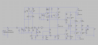
"Old Schematic"
The amp is called NoHyprid ... and guess a Hyprid version will follow. But first I want to build up conventional with Transistors before I throw in some tubes. Thats why i use NPN BJT in the input stage.
The input is a cascode working on a current mirror. Followed by a EF-VAS (that was rather new to me - thanks Douglas Self).
The output is build up conventionally by 2-stage emitter followers. Power BJT are not chosen jet.
The current and the voltage amplifiers have separate supplies.
Thanks for replies and critics and comments!
Update:
Implementing DC-offset correction Post Nr 16
Update History
2019-03-20: Implementing DC-offset correction Post Nr 16
2019-03-18: Implementing the Vbe multiplier and the current limiting. Post Nr 15
2019-03-16: after a while and other projects, I am back to this one and changed the topology: Post Nr 11
Orginal Post / Start:
Hi there,
Here is my first design of upcoming project. A lot is based upon Douglas Self Book and other, earlier Amps which I made. But I am really interessted in your Ideas.
"Old Schematic"
The amp is called NoHyprid ... and guess a Hyprid version will follow. But first I want to build up conventional with Transistors before I throw in some tubes. Thats why i use NPN BJT in the input stage.
The input is a cascode working on a current mirror. Followed by a EF-VAS (that was rather new to me - thanks Douglas Self).
The output is build up conventionally by 2-stage emitter followers. Power BJT are not chosen jet.
The current and the voltage amplifiers have separate supplies.
Thanks for replies and critics and comments!
Last edited:
Q11 which forms a CFP with with Q10 is not necessary, while it may reduce distortion at low frequencies a little which I doubt, it will increase high frequency distortion due to higher device capacitance.
The cascoding of the LTP is also unnecessary if the devices have highish Vce. The cascode reduces distortion very little, if at all and may actually worsen it in some cases. If you reference the cascode to the LTP emitters the cascode will become useful and reduce distortion. Instead of the cascode you could use one more active device and make the mirror a EF augmentated one. This will reduce THD noticeably.
Its better to use higher hfe transistors for the LTP than the 2n5550 as this will reduce offset currents and reduce distortion.
If youre going to use the cascodes Q3 and Q4 use high early voltage and low Cob transistors such as 2n5551. R15 should be connected to the positive supply and R16 to Q7 collector. Also 2n5551 is better choice for Q7.
MJE340 is not good as Vbe multiplier, use a high Hfe transistor, even types like BD139 usually display better hfe. Low voltage transistor can be used here. High hfe lowers the impedance and is more temperature sensitive. Also try a better transistor for the vas CCS, something like 2sa3503, what you should look at is high early voltage and low Cob transistor. BD139 would be improvement here too.
MJE340 is not good as Vbe multiplier, use a high Hfe transistor, even types like BD139 usually display better hfe. Low voltage transistor can be used here. High hfe lowers the impedance and is more temperature sensitive. Also try a better transistor for the vas CCS, something like 2sa3503, what you should look at is high early voltage and low Cob transistor. BD139 would be improvement here too.
add a protection resistor between Q9 collector and ground. 1k to 2k would do. There is a recent Thread showing 10k here. Many use 0r0 and risk blowing up the device during clipping.
Does Q11 follower give some of the benefits of a triple output stage without the risk of stability margins going awry?
Does Q11 follower give some of the benefits of a triple output stage without the risk of stability margins going awry?
Andrew, it does a little, however keep in mind that now you have higher device capacitance to deal with. Although you may well see THD improvement at low frequencies, your high frequency THD, above about 1Khz will most likely be worse. When one uses beta enhancement there is no point in that cfp.
Whats the problem with triple output stages, I find no problems with them. One could use Q11 but with its emitter connected to the positive rail and its collector than connected to another CCS. Indeed some use this scheme as it results in a harmonic profile favoured by some of higher 2nd and even harmonics. In a couple of models by cambridge this was used if I remember correctly.
Sanction the protection resistor, overlooked that.
Hi, many thanks for your comments!!!
As i said, one of the reason for Q11 is the possible translation into a hyprid tube version. But also to have enough current for the outputstage. Of course, a triple outputstage is not that complicated, but might be for the hyprid version. Also its not needed for the goal of power.
R15 is should add a bit local feedback into the input stage. Bad idea?
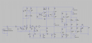
Well, some times passed by. This one never got out of the simulation, so I started again and need to finish till summer. The goal is to have a board which supports BJT or tubes as input devices.
Any thoughts? Simulation works pretty well, but was not easy to get the OPs stable. Real world test will be exciting
Vbe multiplier and protection parts are missing at the moment.
Any thoughts? Simulation works pretty well, but was not easy to get the OPs stable. Real world test will be exciting
Vbe multiplier and protection parts are missing at the moment.
Attachments
Last edited:
Not quite sure if the sims are realistic, but THD seems to be very nice:
for the tube/BJT hyprid:
Total Harmonic Distortion: 0.000714% (0.00057% 2nd; 0,00006% 3rd, and 0.0001% 4th) @200W and 4ohms
for the BJT version:
Total Harmonic Distortion: 0.000926% @200W and 4ohms; manly 3rd order
funny, that the tube version has lower harmonics. I guess these results are way to good to be realistic, but it seems that the circut will work.
Will do some versions with Mosfets...
If you are hoping to build a "bootstrapped cascode" for the input stage, so that VCE of the input transistors Q0a and Q0b remains fixed and constant even when the input signal is a 1 kHz sinewave swinging ± 1.5 volts ....
then the 1uF capacitor "C2" is hurting, not helping. You want the emitters of the cascode transistors Q2a, Q2b to exactly follow the emitters of the differential pair. C2 hurts this.
then the 1uF capacitor "C2" is hurting, not helping. You want the emitters of the cascode transistors Q2a, Q2b to exactly follow the emitters of the differential pair. C2 hurts this.
If you are hoping to build a "bootstrapped cascode" for the input stage, so that VCE of the input transistors Q0a and Q0b remains fixed and constant even when the input signal is a 1 kHz sinewave swinging ± 1.5 volts ....
then the 1uF capacitor "C2" is hurting, not helping. You want the emitters of the cascode transistors Q2a, Q2b to exactly follow the emitters of the differential pair. C2 hurts this.
Thanks, for your comment! Actually I am aware of it, and I tried different things with the tube input. It seems, that a triode with low anode resistance, works better this way. Not sure about it. For the BJT input you are of course absolutely right and I will change that. Thanks!
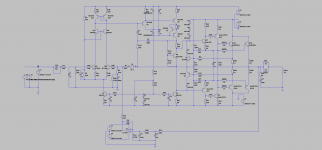
Hi there,
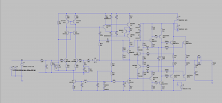
today's task: implementing the Vbe multiplier and the current limiting. I also changed the pre-pre-driver to MJE340/350 to be on the safe side.
The triple output is a bit tricky to get stable; also with the current limiting circuit. Would be pleased of every input to get it even further stable. Now in simulation it works great, but I am afraid, the real world looks different.
Actually its my first triple output stage.
Also changed the VA-feedback into output inclusive circuit. Seems to be way more stable. Simulations with the tube input stage will follow. Also OPs with Mos-Fets and Quasi-complimentary.
Attachments
- Status
- This old topic is closed. If you want to reopen this topic, contact a moderator using the "Report Post" button.
- Home
- Amplifiers
- Solid State
- 150W@8Ohm based on Blameless