thanks woody for sharing.
as for the 3-pieces braces in page1, did you make them out of solid panel or holed panel?
They are solid.
Nice work there!
Did you measure impedance vs. frequency? The results should indicate whether or not you achieved the 40 Hz tuning.
No, i didn't. Yet! I have to build a little circuit for my measurings system, and i don't have the time for it. But i think, eventually the freq.response is what matters. My first goal was the f3 point of 40hz, and by the meuasurings it is at ca. 37-38 Hz.
Actually the TH tuning freq. is at 34Hz , and the drivers fs is 36 Hz. I know, higher driver fs would be better, but i haven't been brave enough to choose a midbass driver with 40+ fs, but lower xmax etc. etc.
THX
No... It is the Warnex textured lacquer... like this.
Its very hard, u cant sctratch it, is waterproof and it still looks good ... I think this is the best choice for PA boxes.
Looks great, I need to use some of this for a similar project. Do you know roughly how much (Kgs) you used to cover both cabs?
No, i didn't. Yet! I have to build a little circuit for my measurings system, and i don't have the time for it.
I'm particularly interested in Fc. While the impedance plot will show it (it will be at the first impedance minimum), it can also be ascertained by running low frequency test tones through the TH, observing the driver's excursion and determine at which tone the driver's excursion is at a minimum.
But i think, eventually the freq.response is what matters. My first goal was the f3 point of 40hz, and by the meuasurings it is at ca. 37-38 Hz.
No argument there, but frequency response can be greatly affected by several different variables, including calibration of the measuring equipment. The impedance plot can quickly indicate how close the built TH is to the HornResp specifications.
Actually the TH tuning freq. is at 34Hz , and the drivers fs is 36 Hz. I know, higher driver fs would be better, but i haven't been brave enough to choose a midbass driver with 40+ fs, but lower xmax etc. etc.
This image you posted suggests Fc is at 40 Hz:
An externally hosted image should be here but it was not working when we last tested it.
Looks great, I need to use some of this for a similar project. Do you know roughly how much (Kgs) you used to cover both cabs?
Thx!
I used 5 Kgs. U can calculate with roughly 1–1,2 Kg/m2.
This image you posted suggests Fc is at 40 Hz:
An externally hosted image should be here but it was not working when we last tested it.
Correct me if i'm wrong, the Fc is the horn cut-off freqency which is defined from the quarter wave frequency of the horn path length ... at a conventional horn.
At a tapped horn it is the path lenght between the front and the back of the driver, wich is here 2,5 m, so roughly 34 Hz.
or not?
Correct me if i'm wrong, the Fc is the horn cut-off freqency which is defined from the quarter wave frequency of the horn path length ... at a conventional horn.
At a tapped horn it is the path lenght between the front and the back of the driver, wich is here 2,5 m, so roughly 34 Hz.
or not?
I think you might be correct. I was incorrectly referring to "Fc" occuring at the lower minimum impedance point as the horn cutoff frequency as my TH sims suggest output dropping quite quickly after that point. Actually even referring to that point as "Fc" is incorrect. In Leach's paper, "Fo" is the horn cutoff frequency and "Fc" is the resonant frequency of the driver in the box (assuming a rear chamber, I suspect).
I'm still interested in that aspect of your TH's performance though, specifically if the frequency of minimum excursion occurs where the HornResp's predictions suggests that it should (~40 Hz).
Question?
Calculating the response accurately is always going to be difficult.
Each bend adds extra volume which can lower the frequency response.
The horn length around the corners is another variable that is not easily accounted for. I have heard that the measurement around the bend should be taken at a radius of 0.7 of the width of the horn.
There are obvious difference between some peoples builds and the hornresp sims, Mosty caused by fitting the horn into a box with parallel walls.
I am tending to sim a reponse.
Then modelling the folded horn in CAD.
Then measuring the physical size of the horn, and using the dimensions to re-sim the horn in Hornresp.
The difficulty is knowing how to deal with the horn length around the corners.
What is the most accurate method for calculating the effective length of a folded horn section?
Actually you will find different approaches for your question, Martin. The reason for your problem is because of different behaviour of the moving air molecules around the folds. Look at a video of an car in a wind tunnel and see how smoke behaves. The smoke close to the car’s surface is dense/compact (high pressure) because the car structure is causing an obstruction. While further away from the car is less dense/compact (lower pressure). To make it more complex, just behind the car you find a vacuum.
When we look to the speed of the air molecules in folded (tapped) horns we see similar behaviour. On the inner side of the fold the air molecules are slower and in the outer side of the fold they have the fastest speed. You are right, some developer's software assumes that 0.7 (although some prefer to use 0,628 as it is 2x π) of the radius in a 180 degree fold seems to be the most 'logical' method because it should imply the most average speed.
However, since every fold in a tapped horn is almost anything from an 90 or 180 degree angle and because of other complex influences air molecules will behave almost every time different. Besides there is more going on between the air molecules. They seem to interact much more complex because of panel resonances, molecules that 'try' to build up standing waves and even some whirlwind type and vacuum effects just behind the sharp edge in a fold. By the time you do figure it all out loudspeaker manufacturers (and maybe even architects, Volkswagen, NASA) but at least this DIY community would be very pleased.
But for the 'old' DIY handyman there is another solution. For instance you can round the sheet (smoothing the edge of the inner side panel to speed up the slowest air molecules and to reduce the whirlwind effect after). Glue some strong acoustic fibre to the outside corner (to slow down the fastest air molecules). Make sure it fits tight otherwise it will land in front of you. Just a layer of +/- 2cm (0.8inch) will do the trick because you don’t want to obstruct the whole path. Of course some designers already use bracing in corners of < 90 degrees which also helps to prevent to build up pressure around these points. If you also put fibre in the longest path on both parallel walls you also can ‘cheat’ a little.
(sorry for the bad grammar)
Thanks for the reply Djim.
There has been some discussion on calculating the folded length in the 'spreadsheet for folded horn layouts thread.'
Soho54 sugested an 'advanced centre line method' in post 13
http://www.diyaudio.com/forums/subwoofers/171747-spreadsheet-folded-horn-layouts-2.html
I have adopted this method at the moment. It has advantages when used with a CAD drawing package as it is possible to use the segment line lengths to generate an associated sketch that has the schematic dimensions ready to input into Hornresp.
The sketch also allows me to measure the optimal width of the horn at each segment end, and the taper angle. By entering these dimensions back into the folded model in an iterative process I am trying to optimise the horn layout!
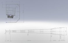
I attach a layout similar to Wood1y,s 15" TH as an example.
There has been some discussion on calculating the folded length in the 'spreadsheet for folded horn layouts thread.'
Soho54 sugested an 'advanced centre line method' in post 13
http://www.diyaudio.com/forums/subwoofers/171747-spreadsheet-folded-horn-layouts-2.html
I have adopted this method at the moment. It has advantages when used with a CAD drawing package as it is possible to use the segment line lengths to generate an associated sketch that has the schematic dimensions ready to input into Hornresp.
The sketch also allows me to measure the optimal width of the horn at each segment end, and the taper angle. By entering these dimensions back into the folded model in an iterative process I am trying to optimise the horn layout!
I attach a layout similar to Wood1y,s 15" TH as an example.
Attachments
what Xmax for smaller driver?
If the 15inch TH uses a driver with 5mm Xmax, then what Xmax does a group of 4 8inch TH need to match the max SPL of the 15inch?
Since the 8inch will be ~half the width, then the volume will be ~half as well.
That ends up with twice the volume for the 4off 8inch TH.
What advantage if any does this doubled volume return?
Last edited:
Sorry for my sarcasm, Martin. I wasn’t aware of the discussion about 'advanced centre line method' (thx for the link). Indeed it sounds interesting what you are trying to do, so I’ll keep my eye on your posts . But still, I would like to see (sometime) that we were able to calculate/visualise the differences in pressure within the folds. Then we could optimise the folds and its airflow to improve efficiency and get less side effects, although... we might end up with some very complex designs to build.
. But still, I would like to see (sometime) that we were able to calculate/visualise the differences in pressure within the folds. Then we could optimise the folds and its airflow to improve efficiency and get less side effects, although... we might end up with some very complex designs to build. I don't know that I would call it "advanced", but it gets the job done. It has worked for every sim posted, with real measurements, that I have used it on.
When talking about a horn subwoofer the difference is so great between the sound waves, and horn dimensions that the sound waves are not relay that perturbed by the small stuff. As long as the 1/4WL of the frequencies involved are greater than the horn dimensions the median path is the best. Once you get into higher frequencies other things start to matter.
Here is a website with measurements/videos of different frequencies passing through a 90deg bend. http://ldsg.snippets.org/HORNS/waves.html
This technique will not show the effects of the acoustic mass/resistance which will alter the Q of the peaks seen in a sim, (HR doesn't allow for this anyway)but they will be at the correct locations, and amplitudes relative to one another. With AkAbak you can use the length to help define your acoustic mass/resistance corner nodes.
I don't know that I would call it "advanced", but it gets the job done.
I referred to it as the "advanced" centerline method to distinguish it from the normal centerline method.
It has worked for every sim posted, with real measurements, that I have used it on.
And this the most important part. I'm seeing very good correlation between predicted and measured results (impedance plot) using this method with my POC #2 TH. Once I have a bit more time, I'm going to check to see if it provides good correlation between the predicted and measured results for my POC #1 TP as well.
It would be interesting though to see if it holds up for horns with very different maximum and minimum path lengths, e.g. horns with asymetric mouths like the BFM Tuba24.
...Did you measure impedance vs. frequency? The results should indicate whether or not you achieved the 40 Hz tuning.
An externally hosted image should be here but it was not working when we last tested it.
You're "the man!" So it seems to me you built what you simmed... do you feel the same way? I guess the lowest imp peak is a bit different.
QUOTE=wood1y;2289368]
QUOTE=wood1y;2289368]
An externally hosted image should be here but it was not working when we last tested it.
[/QUOTE]An externally hosted image should be here but it was not working when we last tested it.
Neat stuff there. Interesting plot. Suggests almost an exponential horn expansion (change your sim to to "Exp" instead of "Con" and have a look at the resulting impedance curve) that's a bit longer than the sim, with perhaps a little bit of panel flex around 90~150 Hz. Nice work...
I dont think this RCF reaches the Xmax limit, even if i drive it with 800 W. Note, that u are playing music, not sinewaves what the hornresp predicts.
For example: The hornresp Displacement graph says, that the excursion of the LF15G401 is 13,2 mm if the total 800W RMS(!) is on a 50 Hz sinewave.. Thats never gonna happen.
Danley is using in a 40Hz TH the B&C 15 TBX 100 which has an xmax value of 9mm, and 1000W power.
Have you or anyone else tried modeling the B&C 15TBX100, Eminence Kappalite 3015LF, BMS 15N850v2 or any others to see how they compare at their full potential? I'm very curious.
I'm very interested in your design, wood1y. Great work! I would do the modeling, but not knowledgeable enough to do so without all the parameters to copy & paste into hornresp as a .txt file.
Indeed he is -- whether this is an issue or not depends very much on the type of music you're playing and how big the amp is, instruments like bass guitar or kick drum probably won't have a problem, synth bass on dubstep (not that I play this but some people do
Since one of the tapped horn advantages is low distortion, it seems a shame to run the risk of adding distortion back again by running out of Xmax -- which is what will happen with the RCF if you do hit it with 800W sinewave at 40Hz, that's why it won't reach 13mm.
Given that they're available, I'd pick a driver with more Xmax -- *if* I was going to drive it heavily -- to make sure this didn't happen. If you're not doing this and don't play music where the bass resembles swept sinewaves then the RCF driver will be fine with 800W, as is the B&C with 1000W (or more on most music).
This is pretty much the only thing slowing me from building this cab. I almost bought parts to do so and this info popped in my head.
Exceeding xmax is a worry of mine as the majority of my shows are dubstep - which have an uncountable amount of sweeping synths in the 40s and 30Hz ranges.
I'm in love with this cabinet's efficiency and output per doller and cu ft., however.
Any thoughts?
Justin
P.S.
Is this driver's xmax not less than 13mm?
Is 800W the maximum amount of power this driver can take before running out of xmax?
Last edited:
(Where'd my 'edit post' button go?)
Is 800W the maximum amount of power this driver can take before running out of xmax? What freq range?
If not, at what power level and at what frequency will damage occur? Remember, these questions are geared towards music that has a lot of energy in the 40 and mid 30Hz freq range.
Justin
Is 800W the maximum amount of power this driver can take before running out of xmax? What freq range?
If not, at what power level and at what frequency will damage occur? Remember, these questions are geared towards music that has a lot of energy in the 40 and mid 30Hz freq range.
Justin
This is pretty much the only thing slowing me from building this cab. I almost bought parts to do so and this info popped in my head.
Exceeding xmax is a worry of mine as the majority of my shows are dubstep - which have an uncountable amount of sweeping synths in the 40s and 30Hz ranges.
I'm in love with this cabinet's efficiency and output per doller and cu ft., however.
Any thoughts?
Justin
P.S.
Is this driver's xmax not less than 13mm?
Is 800W the maximum amount of power this driver can take before running out of xmax?
If you want to go below 40Hz you'll need a bigger box anyway, and in this case you'll definitely run out of Xmax with dubstep. The BMS15N850 is probably the best driver if you want to stick with 15", or if you use an 18" driver to get more volume displacement there are several choices.
The best thing to do is download Hornresp and try some tapped horns to see which driver/horn works best for you (especially box size), it's pretty easy to use.
- Status
- This old topic is closed. If you want to reopen this topic, contact a moderator using the "Report Post" button.
- Home
- Loudspeakers
- Subwoofers
- 15" tapped horn with RCF