I am accumulating parts and knowledge for a 13E1 push pull amp that I will document on this thread.
This will be a design from scratch, other than a push pull amp I have made no design decisions at all. I have read Morgan Jones on the Crystal Palace design (has anybody heard this - how good is it?), the Turner Audio website and the thread on testing 13E1's on this forum.
I am looking for any experience in building with this tube..
I have read Morgan Jones on the Crystal Palace design (has anybody heard this - how good is it?)
I have. It's an excellent amp, but I give away no secrets by noting that Morgan says he'd not use 13E1 again if he were to build another one.
That 13E1 looks roughly like two 6LW6 valves in parallel. Maybe try g2 drive instead for linearity (and so class aB instead, so a lower VDC on g2). Using Vega65's real op. pt. of 25K for gm1, and the tube Mu of 4.5, gives gm2 at 5.5K. (about 2X that of typical TV sweeps)
Getting bolder, we could drive BOTH g1 and g2 with scaled signals (1/Mu) for g1 versus g2. Each grid does half the work now, so the AC voltage swing on g2 gets halved.
Getting even bolder, we note that g2 is operating in grid current territory all the time. So lets drive it with a controlled current drive instead. Tubes have a near constant current gain driven from g2 (constant fraction of plate current intercepted by g2) as long as the plate V does not go much below g2.
With a current drive on g2, we notice that the voltage swing on g2 is now not linear (ignoring polarity inversion) with plate V, but operating with 2/3 power law instead (inverse of the usual 3/2 power law for V to I now, for I to V). So we attenuate the g2 voltage swing by Mu and feed it to g1 too (DC level shifted down to minus V range as well).
Voila! g1 now has linearized current gain as well (2/3 power V drive times 3/2 power V to I for gm1). Mu scaled AC grid voltage swings are halved from g2 drive alone. Tube linearity is now better than g2 drive alone (which is already more linear than g1 drive mode to start with). And highly efficient operation in class aB mode.
(in theory anyway, YRMV)
Last edited:
If you have not looked at it the Turner Audio amplifier runs in pentode with about 20%CFB and a choke loaded differential pair driver. One of my ideas was that that general topology, maybe direct coupled rather than the big caps Turner uses and a Lundahl LL1620CFB as the OPT. The Turner amp has the 13E1s loafing along at 40W on the plates. Like Morgan Jones I have fallen in love with the looks of the 13E1 .. I am so very shallow I know but there you have it 
Also take a look at this 13E1 Valve Bass or HiFi Power Amplifier - ampsnaxes.com. A 13E1 rack mounted bass amp with a separate power supply chassis and the author debates its merits for gigging!! I am in awe...
Smoking: I have to admit your sugestions need some chewing and digesting to
understand..
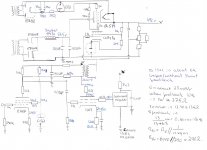
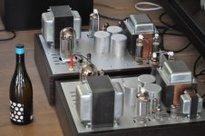
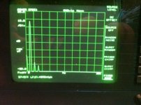
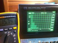
xperse..: added a snapshot of the 13e1se amp and some screenshots of Spectrums at 6 w out, and 31 w out.
I remember that I read Turners description up and down several times
before I decided to choose a more simple topology.
understand..
xperse..: added a snapshot of the 13e1se amp and some screenshots of Spectrums at 6 w out, and 31 w out.
I remember that I read Turners description up and down several times
before I decided to choose a more simple topology.
Attachments
"Smoking: I have to admit your sugestions need some chewing and digesting to understand.."
Screen or g2 drive has certainly been used before, so nothing really new there. It is more "linear" than g1 drive, due to the absence of g1 wire proximity (to cathode) effects. (g2 is close to 3/2 power law, while g1 is close to square law) Screen drive does generally require substantial drive signal on g2 to operate the tube to full power, and some danger exists of over-heating the g2 grid when driving it to maximum voltage while the plate is at minimum voltage.
What is new above is some speculation on splitting the drives between g1 and g2, with the drive voltages scaled by Mu so that each grid does half the control work (g1 gets 1/Mu voltage reduction versus g2). The advantage here is that the voltage swing required on g2 can be halved now for full output current, since g1 is doing half of the heavy lifting. This makes for an easier drive stage ahead of it, and reduces the danger of g2 over-heating.
The final idea is to use current drive to g2, rather than voltage drive for controlling g2, since it approximates constant current gain to the plate current (which would be quite linear versus the usual 3/2 V to I power law for grids). It's only rather approximately linear however, since g2 draws heavier current as the plate voltage reduces.
What is actually called for is a combined V and I (or impedance) drive, since the g2 current gain droops at high current, while the g2 V to I gain increases there (3/2 power law). Combining them would allow for some compensation. (also, the square law at co-driven g1 gives some additional boost) This automatically occurs anyway, when a resistive voltage divider is used between g2 and g1 (and some minus bias point) for the Mu divider. The resistors draw current proportional to g2 voltage, so it ends up a combination V and I, or impedance drive. One would select the amount of current drive versus V drive by the actual values used in the R divider.
Last edited:
It's going to be a long while before I can do this because of work and travel, but the 'smoking amp drive' shall be explored.
I have a couple of those ruinous expensive Apex high voltage op amp and one of my very general plans was to build a high voltage low distortion push pull test jig using a pair. This will allow me to lash up all sorts of drive schemes very quickly.
I have a couple of those ruinous expensive Apex high voltage op amp and one of my very general plans was to build a high voltage low distortion push pull test jig using a pair. This will allow me to lash up all sorts of drive schemes very quickly.
Hi, I am now building a stereo single ended amp, using 13 % CFB and fixed G2 with 1900 ohm primary. I've done some preliminary investigation of this configuration and are getting about 30W at clipping for 80W dissipation in the 13E1. Plate current is 180mA, so the LL 1620 could certainly not support a Class A push pull because of the current. The CFB is also 25% in the Lundahl so you would have a big drive requirement. So you'd end up with largely Class B output stage and a big drive requirement. I'm no guru but it sounds like a poor option.
I am accumulating parts and knowledge for a 13E1 push pull amp that I will document on this thread.
This will be a design from scratch, other than a push pull amp I have made no design decisions at all. I have read Morgan Jones on the Crystal Palace design (has anybody heard this - how good is it?), the Turner Audio website and the thread on testing 13E1's on this forum.
I am looking for any experience in building with this tube..
Where did you find 13E1 tubes?.. They're quite rare / expensive these days I think..
... Plate current is 180mA, so the LL 1620 could certainly not support a Class A push pull because of the current. The CFB is also 25% in the Lundahl so you would have a big drive requirement. So you'd end up with largely Class B output stage and a big drive requirement. I'm no guru but it sounds like a poor option.
I'm not planning to use LL1620 for 13E1, my question was about general approach to usage lundahl LL1620CFB and fixed bias.
I'm not an expert but seems that if cathode is tight to the ground and cathode end of CFB coil is attached to cathode, ground end of CFB coil will be tight to the ground as well so no current will flow
 please correct me if I'm wrong..
What is new above is some speculation on splitting the drives between g1 and g2........This automatically occurs anyway, when a resistive voltage divider is used between g2 and g1
It was speculation when we talked about it 4 years ago. After blowing the screen grid out of a few sweep tubes in screen drive while exploring the upper end of their power range, I decided that pure screen drive was not good for an amp that may be abused.....Since I tend toward amp abuse, I began searching for alternatives.
I have been experimenting with simultaneous G1 and G2 drive ever since. In this thread you will find a schematic of an early prototype that implements 'smoking amp drive' or what I called dual drive.
http://www.diyaudio.com/forums/tube...ed-drive-strawman-design.html?highlight=G1=G2
In the 4 years since I have managed to build one working prototype 100 watt amp, done several dozen simulations, and have a second amp under construction.
When this all started I was working 50 to 60 hours per week trying to keep my job, so there was little time for tubes. During that time I simulated the 100 watt amp, then built it, The amp and simulation matched well.
About a year ago I lost my job of 41 years any way. Tubelab, and all of my equipment was packed up and moved 1200 miles, and is currently in storage. It will be several more months before I have some basic lab equipment set up, and longer before everything is fully rebuilt. I have done several more simulations, laid out several PC boards, and just got one back from the PCB vendor.
As time permits I will build up another dual drive amp, power it up and see what happens. Being a new design with unproven technology (dual drive) I don't expect it to work, and won't have much of a chance for debug for a while. Once I have a fully operational lab, expect much more on this topic.
So far I have learned that with dual drive every different tube type behaves differently in simulation, and some don't work at all (excessive crossover distortion, unstable behavior, or failure to simulate). Since I have only built one physical amp, which did match the simulation, I don't know yet if these results are due to bad tube models, or real problems.
For the resistive divider to work as described, G1 must remain negative under all operating conditions. Near zero or slightly positive operation may help keep the screen current down during the maximum tube current portion of a cycle, but this complicates the driver.
The plate resistance under dual drive conditions is as high or higher that a conventionally (G1) driven pentode. The amp's output impedance without feedback is often higher than the speaker impedance (damping factor less than 1). This causes a significant portion of the amp's power output to be dissipated in the output tube's plate resistance. A considerable amount of feedback will be needed to control this condition. I have needed multiple local feedback loops and some global feedback to make a usable amp with a damping factor of 5 or greater.
The prototype that works, runs at 8 mA per tube idle current on 600 volts and makes 100 watts without any issues. I let it run at that power level for about an hour of continuous sine wave, and there was no tube glow.
I have no knowledge of the 13E1, and no model for them, so I can't tell you how well they will work in this application. I do have a simulation for a dual drive amp using PPP 6LW6's that shows 400 watts per channel, and I have the parts to build it, so only time will tell.....
Re: Cypher:
"I'm not an expert but seems that if cathode is tight to the ground and cathode end of CFB coil is attached to cathode, ground end of CFB coil will be tight to the ground as well so no current will flow please correct me if I'm wrong.."
Not sure what you are figuring there. Normally the cathode puts it current through the CFB winding from ground. Heat wise, it doesn't matter to the OT whether it is cathode or plate current going through it. You still figure the winding resistance times the current squared to get the heat generated. I think the earlier comment was simply about the 13E1 typically drawing LOTs of current.
---------------------------
13E1 looks very similar electrically and physically to 2X 6LW6 tubes in parallel.
----------------------------
I've played around with some g2/g1 dual (ratio'd) drive stuff using the curve tracer here on some TV sweep tubes. The g2 grid typically follows an x=1.3 exponent power law (Vg2 to Ip, ie., Ip = k(Vg)^x ) fairly consistently, while Vg1 drive typically follows a 2.2 to 2.7 exponent power law in the middle of the current range (due to grid wire proximity to cathode effects) (but more like 3.0+ to 1.1 over the full current range). So g2 is looking more linear in voltage drive mode. (not necessarily in P-P though, see below)
As George (Tubelab) mentioned, the trick is in handling crossover distortion effects in class aB and any grid current(s). With the split/dual drive, this is even more of an issue since one would like to bring g1 up positive to avoid heat stress on g2 at signal peaks. (higher peak Vg1 means lower peak Vg2) If g1 crosses from negative to positive territory, then there will be class xx-2 grid current discontinuities to handle too.
From playing with a curve tracer setup, it becomes apparent that voltage drive on either of the grid(s) is expansive (V to I exponent greater 1.0, ie. x= 1.3 and 2.2-2.7, Ip = k(Vg)^x ), while current drive (a high Ohm resistor in series with a positive going grid) is compressive (current gain falling off at high current/low Vp). So one can find a selected impedance for driving the grid(s) that is a balance between these two, to get a near linear drive (over a region anyway).
To make things even more complicated, the g1 power law exponent changes noticeably from low current to high current. If you look at (page 5, top graph in the link below, for) the 300B tube's g1 transconductance, you will see a variation of gm versus current that is typical for many power tube types.
(gm is the 1st derivative of the V to I power law, ie. delta Ip per delta Vg, or the slope, so an x = 2.0 exponent power law plots as a linear 1.0 ramp on the gm curve, the central part of the 300B graph) The S curve shaped ends on the gm plot show that the power law is higher than 2.0 at low current, and less than 2.0 at high current. (so the 300B is mostly acting like a x = 2.0 law Mosfet through most of its central operation zone, an expensive Mosfet)
G2 drive on the other hand keeps a fairly constant exponent throughout the operating region. But since it's power law exponent is around 1.3 typically, it's gm would plot like the top curved part of the 300B S curve everywhere (ie, drooped over).
For the P-P case, you get another gm curve set flipped around, with grid bias voltage selected overlap. Your objective is to get the two tube gm curves to sum to a constant gm throughout the operation region for least general distortion and crossover dist. (Obviously, the 300B works beautifully in class A with those symmetrical gm S curves. And then triode internal feedback improves further yet.)
With g2 or g2/g1 drive, one will typically be trying to run class aB, so this constant gm sum gets much more difficult to achieve without the full overlap.
With dual g2/g1 drives in P-P you get 4 total gm curves to sum up. A g1 S like curve and a g2 drooped over curve facing each way (ie, each tube). Tools available include both g1 and g2 separate biasing for overlap, impedance drive of positive grids (lowers the power law, which makes the gm droop over once under x= 2.0 P-L) And one can put an R in the cathode circuit which has a similar effect on both grids of lowering the power law.
The -ONE- thing in your favor using TV Sweeps here is their x > 2.0 Vg1 power law. (2.2 to 2.7 typical), since you can play that upward curving gm1 against the downward curving gm2.
Clearly some design challenges with this scheme to work out yet.
http://frank.pocnet.net/sheets/084/3/300B.pdf
Last edited:
Some recent blue sky thinking (murky daydreaming maybe) on this split/dual g2/g1 drive approach.
I have been analyzing the grid power law for various Sweep tubes and other notable tubes (like 300B) recently and some curious things emerge.
The nominal textbook grid power law is 3/2 power (Child/Langmuir formulas). But the TV sweeps typically have 1.1 to 1.33 power law for g2 and a 2.0 to 2.9 power law for g1 depending on tube type.
But 300B has a 1.5 power law for its plate, and a 2.0 power law for g1 (over most of its operating region anyway). So why would the g2 law in the sweeps be lower than 1.5, since g2 is spaced about the same as the plate for the 300B? If anything, since g2 has grid wires, you would expect something a little in excess of 1.5, but no.......it doesn't.
Well, the g1 gets its higher power law from grid wire proximity effects to the cathode. I think what is happening in the sweeps for g2 is due to g1 and g2 being grid wire aligned. The g1 wires are SHIELDING the cathode from the direct g2 wire effects, giving an ANTI-grid wire proximity effect. So the g2 power law drops from 1.5 instead of increasing as it does for g1.
Now the interesting point of all this speculation:
For dual internal Mu scaled g2/g1 drive, the g2 will be generating the same electrical field at the cathode as g1, since both grids are doing equal work. That means that g2 is developing the same potential field at the g1 spacing that g1 is generating itself. And that means that the cathode does NOT see any g1 grid wire proximity effect, because it then sees a uniform field potential everywhere.
So g1 should then have its power law dropped back to the nominal 1.5. And g2 should similarly not be 1.33, but instead still the nominal 1.5 power law. The two grids are acting together like a uniform plate.
This means one gets a tube that is more "linear" than the 300B with its 2.0 power law g1 (1.5 versus 2.0). Useful for SE application. But for P-P, we would like 2.0 power law (at least for class A P-P) to get constant gm sum from the two tubes.
Well, the exact Mu scaling (g2/g1 internal Mu) got us 1.5 power law. And g1 alone (equivalent to a very high Mu scaling) gets us the original 2.0 to 2.9 g1 power law, depending on the tube. So.....If one adjusts the g2/g1 drive scaling above the internal Mu factor, one should be able to adjust the effective total g2/g1 power law to something in between 1.5 and 2.0 to 2.9. So an adjustable drive splitting/scaling pot should be able to get us exactly 2.0 power law for a perfect class A P-P constant gm sum. So the TV Sweeps can be "tuned" to be perfect 300Bs.
Some testing is obviously in order.........
Last edited:
Some testing is obviously in order.........
One driver stage, two mosfets with adjustable DC bias and AC gain pots for each grid. Times two, one set for each tube in P-P. Got it, built it already.....It's in a box on a shelf in a warehouse somewhere. I saw it work for a day as I was packing up to leave Florida.
Now I just need my lab back, but I won't have the keys to the new house for over a month, depending on weather. After that, we need to move everything that we have stored in several locations into the house, and arrange it all to achieve suitable WAF. Then I can start building out the basement where the lab will go. Then build a new lab.......It will be a while.
- Status
- This old topic is closed. If you want to reopen this topic, contact a moderator using the "Report Post" button.
- Home
- Amplifiers
- Tubes / Valves
- 13E1 Push Pull