After having succesfully built SY's RDL I am hungry for more.
I am planning to design and build a push-pull amp with 6C4C DHT triodes.
Some reqs / limitations
1. Tubes easily available
2. Dual mono approach
3. Use of 2 PSU transformers. each 2 x 320V 0.1A, 6.3V 2A, 12,6V 1A
4. 12 W output push-pull
5. 6C4C to be easily replaced with 6L6 (6p3s-e)
6. Silicon devices allowed: LEDs, FETs or BJTs.
7. CCS for heaters
8. Regulated voltage for a voltage amp and a phase splitter
9. LED biased output tubes
10. Size of a chassis
I think of some tubes I own to be used:
- voltage amp Phillips Miniwatt ECC81 and E80CC, Tesla E88CC, Russian 6H9C, Siemens C3g
- phase splitter Edicron E182CC, Russian: 6C45, 6C4, 6H8C
However, PT has 12,6V winding which limits the use to smoe of the above.
I feel E80CC as a voltage and E182CC as an LTP is a starting point.
- voltage amp Phillips Miniwatt ECC81 and E80CC, Tesla E88CC, Russian 6H9C, Siemens C3g
- phase splitter Edicron E182CC, Russian: 6C45, 6C4, 6H8C
However, PT has 12,6V winding which limits the use to smoe of the above.
I feel E80CC as a voltage and E182CC as an LTP is a starting point.
Member
Joined 2009
Paid Member
hey-Hey!!!,
The last few DH PP amps I build with 1 heater trans for each tube, and one hum pot across it for each tube. 2.5V to 12V to heat( 1619, HY69, 4E27, 813, HY1269 ) and no hum at all. Don't go to trouble to rectify DC for DH PP. Watch dissipation in hum pot.
cheers,
Douglas
The last few DH PP amps I build with 1 heater trans for each tube, and one hum pot across it for each tube. 2.5V to 12V to heat( 1619, HY69, 4E27, 813, HY1269 ) and no hum at all. Don't go to trouble to rectify DC for DH PP. Watch dissipation in hum pot.
cheers,
Douglas
I have a bunch of these tubes so I'll be watching your development !
I've listened to a SE fixed bias 6C4C driven via an interstage trafo and it sounds good. Main complaint is hum, but with PP you can wire the two heaters in anti-phase.
A bit OT, still you may be interested in S. Bench's approach to hum cancellation
Effects of AC Heating Power Applied to Directly Heated Triodes
PSU for output triodes
Now, I need to choose proper HT PSU for output tubes. I am not certain what is current requirements while voltage at grid changes from 0 to max.
Assume ug = 0 (or Ug = -65V), then Ib = 2x 40 mA and Ub = 400V.
When Ug1=0V and Ug2 = -130V, then Ib = 75 mA + 0 mA, because one triode does not conduct? Shortly, can I use a current source of 80mA as a model for a load to PSU?
Why is it important? One reason is choke impedance in series with the load, the more current, the more voltage drop.
Last edited:
PSUDII Sim of output stage
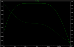
I have done quick simulation using PSUDII. At t=3s 2 x 70 mA current is drawn. See attachement._led.png")
I will verify voltages and response to the load after having built. Instead of 1N4007, 1N5062 sintered glass avalanche diode will be used. If full wave circuit employed - 2 rectifiers must be connected in series - repetitive reverse voltage for 1N5062 is 800V which is exceeded. With Graetz bridge it is 415V.
I don't assume another PSU for voltage amp and driver. Yet HT regulator will be used
I have done quick simulation using PSUDII. At t=3s 2 x 70 mA current is drawn. See attachement.
I will verify voltages and response to the load after having built. Instead of 1N4007, 1N5062 sintered glass avalanche diode will be used. If full wave circuit employed - 2 rectifiers must be connected in series - repetitive reverse voltage for 1N5062 is 800V which is exceeded. With Graetz bridge it is 415V.
I don't assume another PSU for voltage amp and driver. Yet HT regulator will be used
Last edited:
Driver / phase splitter
Input capacitance of 6C4C consists of
Cin = Cstray + Cm = Cstray + Cgk +Cgp*(1+u) = 10pF + 7,5pF + 16,5pF*5,1 = 101,6pF round to 100pF.
Source impedance of a driver stage
rs = 1/(2*pi*f*Cin) = 1,59 k, where f=100kHz
Output impedance of an E182CC-based LTP is around 1,54k with plate resistors of 47k. Which should be fine.
Voltage amplification of LTP is about 11,8 in reference to gnd. Provided I need 130Vp-p or 46Vrms to drive 6C4C, voltage preamp stage is required.
LTP with some feedback to improve signal symmetry (Thanks Geek) and constant current sink as a tail will be used
Last edited:
First simulation of LTP and output stage with LEDs
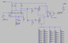
Phase splitter (LTP+simple CCS) and output stage with LED matrix. That is first approach and LTP may change when voltage amp is added. I still have troubles with 6C4C P G H1 H2 spice model to be used with LTSpice. For now simplified version with virtual cathode. There are 20 x 5 LEDs used in the 6C4C bias, which gives ca. 65V voltage drop DC and Ua=386V-65V=321V.
I think if cheap red LEDs are used I need 5-6 more in each chain. I have already had two 4 x 26 LED matrices which were used with SE stage - I will reuse them.
PS.
If anyone has cheap red LED spice model, PW or post here. TIA
Attachments
Last edited:
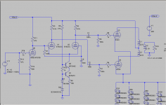
I want DC couple the first stage to the LTP, which needs elevating potential on cathodes of E182CCs. Cascoded NPNs will be used. That in turn will increase CCS AC impedance 3 magnitude order (initially max. 200k).
E182CC is said to work @Ua=150V. I need 130V anode voltage swing and 150V of Ua then 120V + Ugk(E182CC) is left. Say, 126 - 134V on the anode of the first stage.
E182CC is said to work @Ua=150V. I need 130V anode voltage swing and 150V of Ua then 120V + Ugk(E182CC) is left. Say, 126 - 134V on the anode of the first stage.
Last edited:
Ready for breadboard phase and tests
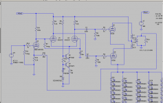
Initially I wanted to use E80CC, yet decided to change to Russian 6H8C (6N8S = 6SN7 equiv). That implies change of heater supply.
I am eager to start breadborading. Weekend ahead.
Any comments welcome.
Initially I wanted to use E80CC, yet decided to change to Russian 6H8C (6N8S = 6SN7 equiv). That implies change of heater supply.
I am eager to start breadborading. Weekend ahead.
Any comments welcome.
Attachments
I recommend you to use 2 x EC91 in a simple non-balancing phase splitter/driver.
That means a different project, for a different thread.
That means a different project, for a different thread.
Correct.
- Status
- This old topic is closed. If you want to reopen this topic, contact a moderator using the "Report Post" button.
- Home
- Amplifiers
- Tubes / Valves
- 12W Push pull w/6C4C