domjun said:I just wonder what exactly in the top of your list for line stage preamp.
Is it one of these tubes: 6N30P or 6NP or 12BH7A?
Thanks for your opinion.
Nope,
 My current faves are all dhts 01, 12, and 26 not necessarily in that order. I would also include the 6SN7 and 6J5 in my "second tier." And I use transformers...
I don't usually look for opportunities to use GNF but this might be an instance where it would be appropriate. If we are talking line preamp why not a standard CC stage direct coupled to CF with global negative feedback from the output of the CF back to the CC stage to control the excessive gain of the 12AX7.
kevinkr said:
Nope,
Of course you're right.
I have received a pair of 26 from Netherland. Hope I could make them sings in the near time
But the first try would be without transformers
Yes Jerluwoo, that is the kind of thing I had in mind. I have heard that the AX7 does better with higher B+ and larger plate load but I have not actually tested that theory. I think that SY mentioned something on the order of 200K+ on the plates for best linearity but I think you might want to go for a larger HT in that case. Maybe SY will chime in with some definitive guidance in that regard.
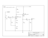
Here is a circuit that I designed long ago that you might find interesting - it's a good performer and very simple.
You need 300V of well filtered dc to make this design work optimally.
Please note this design is for personal use only. No commercial use permitted.. Legal boiler plate. (The design comes out of my old pre-amp project book which is still available.)
Gain is about 20dB..
Input impedance of amplifier used with this design or any design based on a single 12AX7A for that matter should be >70K. Output Z is ~1.5K.
An unregulated but well filtered supply is required. A 6X4 or 6V4 rectifier tube should be adequate for the 5mA required. The filament supply for this design should be dc to minimize hum and buzz coupling to the cathode circuit as this is not a low impedance node.
The transformer could be a 500VCT @ 20mA or so, with a single filament supply of 6.3V@1A for the rectifier.
I recommend a separate 12.6Vdc floating filament supply. You can use a 16V@1A transformer driving a bridge and a 4700uF/16V cap. This feeds a heatsinked 7812 with a 1N4148 diode in series with its ground lead to give 12.6V, a single 10uF cap across the output should be sufficient.
Note that I said the filament supply is floating - this is because the negative side of the supply is tied to a voltage divider between B+ and ground.
The voltage divider consists of 3 components, a 249K resistor connected to B+ on one side and to a 10uF/100V Cap (+) and 49.9K resistor in parallel. The other end of both the cap and 49.9K resistor are grounded. Connect the negative side of the filament supply to the point common to all three parts. Use only pins 4, and 5 for 12.6V operation with the 12AX7A. This will bias the filament supply to 50V.
Several former clients built this pre-amp and with care it can sound very good indeed.
You need 300V of well filtered dc to make this design work optimally.
Please note this design is for personal use only. No commercial use permitted.. Legal boiler plate.
(The design comes out of my old pre-amp project book which is still available.)Gain is about 20dB..
Input impedance of amplifier used with this design or any design based on a single 12AX7A for that matter should be >70K. Output Z is ~1.5K.
An unregulated but well filtered supply is required. A 6X4 or 6V4 rectifier tube should be adequate for the 5mA required. The filament supply for this design should be dc to minimize hum and buzz coupling to the cathode circuit as this is not a low impedance node.
The transformer could be a 500VCT @ 20mA or so, with a single filament supply of 6.3V@1A for the rectifier.
I recommend a separate 12.6Vdc floating filament supply. You can use a 16V@1A transformer driving a bridge and a 4700uF/16V cap. This feeds a heatsinked 7812 with a 1N4148 diode in series with its ground lead to give 12.6V, a single 10uF cap across the output should be sufficient.
Note that I said the filament supply is floating - this is because the negative side of the supply is tied to a voltage divider between B+ and ground.
The voltage divider consists of 3 components, a 249K resistor connected to B+ on one side and to a 10uF/100V Cap (+) and 49.9K resistor in parallel. The other end of both the cap and 49.9K resistor are grounded. Connect the negative side of the filament supply to the point common to all three parts. Use only pins 4, and 5 for 12.6V operation with the 12AX7A. This will bias the filament supply to 50V.
Several former clients built this pre-amp and with care it can sound very good indeed.
Attachments
thanks Kevinkr. the PT you said that is 500VDC at 20ma. , Does it support one side or both side....... I prefer to put them all in one Chassis. ........kevinkr said:Here is a circuit that I designed long ago that you might find interesting - it's a good performer and very simple.
You need 300V of well filtered dc to make this design work optimally.
Please note this design is for personal use only. No commercial use permitted.. Legal boiler plate.
Gain is about 20dB..
Input impedance of amplifier used with this design or any design based on a single 12AX7A for that matter should be >70K. Output Z is ~1.5K.
An unregulated but well filtered supply is required. A 6X4 or 6V4 rectifier tube should be adequate for the 5mA required. The filament supply for this design should be dc to minimize hum and buzz coupling to the cathode circuit as this is not a low impedance node.
The transformer could be a 500VCT @ 20mA or so, with a single filament supply of 6.3V@1A for the rectifier.
I recommend a separate 12.6Vdc floating filament supply. You can use a 16V@1A transformer driving a bridge and a 4700uF/16V cap. This feeds a heatsinked 7812 with a 1N4148 diode in series with its ground lead to give 12.6V, a single 10uF cap across the output should be sufficient.
Note that I said the filament supply is floating - this is because the negative side of the supply is tied to a voltage divider between B+ and ground.
The voltage divider consists of 3 components, a 249K resistor connected to B+ on one side and to a 10uF/100V Cap (+) and 49.9K resistor in parallel. The other end of both the cap and 49.9K resistor are grounded. Connect the negative side of the filament supply to the point common to all three parts. Use only pins 4, and 5 for 12.6V operation with the 12AX7A. This will bias the filament supply to 50V.
Several former clients built this pre-amp and with care it can sound very good indeed.
MQracing said:
what's happening on it ?//

longji98 said:
thanks Kevinkr. the PT you said that is 500VDC at 20ma. , Does it support one side or both side....... I prefer to put them all in one Chassis. ........
Yep, supports both channels..
Thanks Kevin. , , it is very helpful for me. thanks a lolkevinkr said:
Yep, supports both channels..
longji98 said:
what's happening on it ?//
Hello. Not sure what your asking or commenting on....
I hope that's not tears I'm seeing
It's a relatively straightforward circuit.... with published test results...
and the author also provides two alternative strategies (tube types) in the same basic configuration.
MSL
longji98 said:by the way, I am also looking for one 24 Step plated attenuator kit. ... any suggestion about it? thanks.
do a websearch for DACT and Goldpoint.
If cost is a consideration--- you might also want to look at the PEC-- though not a stepped attenuator--- many people report favorably on it's sound quality.
MSL
- Status
- This old topic is closed. If you want to reopen this topic, contact a moderator using the "Report Post" button.
- Home
- Amplifiers
- Tubes / Valves
- 12ax7 preamp.