Why you like to use a SRPP? Why you don't use a WHITE CATHODE FOLLOWER? If you use a CF, you will have a small output impedance.
If you use a SRPP you will have a amplification of the half of the Mu of down tube...
The Cathode Follower, is a buffer unit, but SRPP isn't it.
Best Regards,
Felipe
If you use a SRPP you will have a amplification of the half of the Mu of down tube...
The Cathode Follower, is a buffer unit, but SRPP isn't it.
Best Regards,
Felipe
Thanks for your answer. Problem is that such I already have.
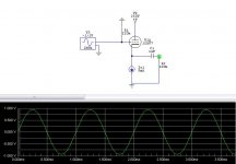
I am looking for something along the lines of the circuit attached and described as a buffer. Wanna do something creative with that second triode in the lil bottle you see...
Although when I simulated it in CircuitMaker it showed gain. If Frank is wrong about it being a buffer I am wrong asking for a buffer.
Attachments
It was described as an SRPP buffer when they discussed it if I remember correctly. Or a grid lick bias something. Interestingly, it gives gain in CircuitMaker. But I remember that Frank said its a buffer. Frank is a regular here, I hope he spots the thread and will enlighten us. 12BH7 I have 2 types. One pair EH, one pair GE NOS. 12AU7 I have 10s of yummy NOS treasures so I wanna use 12AU7 so to change colors. Optimized White cathode follower with Ra=Rp/mu another good suggestion maybe? Does it sound really good vs single ended ccsed cathode follower?
Tweeker said:It looks like a White Cathode Follower with an extra resistor and unbypassed cathode resistor at the bottom. These increase ZO and perhaps linearity.
...That uses grid lick bias too. Why I remember something about SRPP being stated its odd. I need holidays.

Nice link Tweeker! Thanks! Aha! the Aikido uses White cathode follower 2nd stage with newer formula suggestions. This is a well reviewed pre. I need second stage only.
Hi sorenj07,
A lowish Zout is not everything; you also need current going to drive a voltage swing into a load. P=U*I.
Regards,
Tom
sorenj07 said:I recently modeled a White CF for use as a headphone amp using 12AU7's, I can scan it when I get home if you want. Zout = 38 ohms.
A lowish Zout is not everything; you also need current going to drive a voltage swing into a load. P=U*I.
Regards,
Tom
sorenj07 said:I recently modeled a White CF for use as a headphone amp using 12AU7's, I can scan it when I get home if you want. Zout = 38 ohms.
Please do by all means. Thanks. People here will evaluate it for us.
An externally hosted image should be here but it was not working when we last tested it.
I think it'll be able to supply some decent current as well.
Hi sorenj07,
the circuit you show, at outputs, has ca. 50nF * 47k RC filter. When unloaded, a corner frequency of about 70Hz will result.
Loading the output with a typical line stage load of maybe 100k (in parallel with the 47k) will give a corner freq of about 100Hz.
A typical hi-Z 500 ohms headphone load will result in a corner freq of 6kHz or something.
Doesn´t make sense to me somehow, so I suppose I am completely wrong or do miss something important?
Regards,
Tom
Tubes4e4 said:the circuit you show, at outputs, has ca. 50nF * 47k RC filter.
Maybe you're missing the 4.7uF caps?
Umm, how are you calculating this frequency? Tube CAD listed output impedance as like 38 ohms for the output stage, and bandwidth was a fraction of a Hz to many hundreds of KHz.. I'll take another look when I get home, though.
Its a simple RC highpass, use the load and capacitor as inputs. Add the source resistance if you like.
f = 1/(2*pi*R*C)
Simple R-C Filter Cutoff.
Bandwidth of the amp is that wide, up till you get to that filter. If your an elcophobe with 200 ohm+ phones, try using an oil motor run cap.

Sorry, that's all I've got :\salas said:Can you show a single ended single stage portion for driving 100K?
Tweeker said:Its a simple RC highpass, use the load and capacitor as inputs. Add the source resistance if you like.
f = 1/(2*pi*R*C)
Simple R-C Filter Cutoff.
Bandwidth of the amp is that wide, up till you get to that filter. If your an elcophobe with 200 ohm+ phones, try using an oil motor run cap.
By this calculation, the frequency of the filter is .72 Hz.
1/(2*pi*47000 ohms*.0000047 farads). I'm having a hard time figuring out why a highpass filter at .7 Hz would limit my bass in any conceivable fashion...
edit: paralleling 32-ohm headphones to the 47K load results in a resistance of a tiny bit less than 32. Do I recalculate a new filter based on this? in that case, my highpass frequency is at 1058 Hz, which is pretty wretched. I hope I'm wrong?
- Status
- This old topic is closed. If you want to reopen this topic, contact a moderator using the "Report Post" button.
- Home
- Amplifiers
- Tubes / Valves
- 12AU7 SRPP buffer suggestions