Well I'm assembling one of these gems and haven't seen much info on how the rectifiers are assembled (types, specs, etc.) <br />
<br />
I have a diesel truck that sits a lot. I was late with installing my solar trickle/desulfator and the batts (yes two of them, type 65 1000CCA ea!) are certainly sulfed up. (~12.0v at rest <img src="http://files.diyaudio.com/forums/images/smilies/frown.gif" border="0" alt="" title="Frown" smilieid="11" class="inlineimg" />)<br />
<br />
I'm not trying to scrounge parts or build for pennies, I'm purchasing new components and so far have a 0.22ohm MFR, 1W @5% (fuse), one 4.7ohm Wirewound resistor, 5W @5% (reverse protection), and one 7.5uF Run/Start Cap, 370VAC @ 5%. Now I just need rectification <img src="http://files.diyaudio.com/forums/images/smilies/wink.gif" border="0" alt="" title="Wink" smilieid="4" class="inlineimg" />. I considered gutting one of my old PC power supplies, but I'm not sure I'd have success.<br />
<br />
I was going to use the PC power supply to charge after I desulfated because I've lost confidence in automotive charges. I have an older Sears 70/12/2 6/12v "smart" charger, it just swings the amp meter wildly with the "charged" light flickering on and off. Probably due to the sulfated plates causing the charger an over volt condition... don't know. Anyway, thanks to all for the great, informative, hard to kill thread! <img src="http://files.diyaudio.com/forums/images/smilies/biggrin.gif" border="0" alt="" title="Big Grin" smilieid="3" class="inlineimg" />
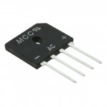
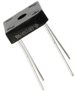
I guess my post was too far back (started this thread resurrection), I'm no EE, but pretty handy. I've got an old alt. rectifier which seems WAY overkill for such a project. Is there a rectifier that's usable in a garden variety PC power supply that I could use? I'm not exactly sure what I'm looking for, as the diodes will/should be different in the PwrSup than in the Alt. rectifier. Also, I thought I had to get a big cap (run/start) and connect in parallel with the A/C circuit, these recent schematics show the caps in series
 .
.

I'm surprised this this thread has run so long... the thread that won't die. Trouble is, some person who attempts to build these "gadgets" might.It contravenes every rule in the book.
Not only is it lethal from the perspective of being directly mains powered and therefore unisolated, it also has the potential (literally) to get you when the output terminals are not connected to a battery.
Imagine someone feeding 120 or 240 volts into a bridge rectifier where the output is just a couple of wires with croc clips on the end. Imagine the capacitor version where a cap fails short.
So its thread closed.
- Status
- Not open for further replies.