Maybe explain in more detail what you want to do . Like why do you need -12v ??
Most op amps, e.g. TL071 run on "dual rail" (e.g. + 12 and -12 volts) I have +12. Need - 12 for TL071
Last edited:
How much current or power is available from your existing 12-Volt supply? What type of supply is it?
Also, there are several other possible (and possibly better) ways to obtain or build a bi-polar bench supply. Are you looking for the cheapest way, or the easiest way, or would a better way be something that you would want to consider?
Also, there are several other possible (and possibly better) ways to obtain or build a bi-polar bench supply. Are you looking for the cheapest way, or the easiest way, or would a better way be something that you would want to consider?
I might be tempted to buy a DC-DC converter module. For maximum quality, I'd use one with +/-15V outputs and regulate down to +/- 12V with linear regulators.
MC34063 switching regulators are found in nearly every car cellphone and USB charger. The application note clearly shows how to hook one up for negative output, and board layouts are provided, if you can't easily alter the charger layout.
http://www.onsemi.com/pub_link/Collateral/MC34063A-D.PDF
MC34063 switching regulators are found in nearly every car cellphone and USB charger. The application note clearly shows how to hook one up for negative output, and board layouts are provided, if you can't easily alter the charger layout.
http://www.onsemi.com/pub_link/Collateral/MC34063A-D.PDF
How much current or power is available from your existing 12-Volt supply? What type of supply is it?
Also, there are several other possible (and possibly better) ways to obtain or build a bi-polar bench supply. Are you looking for the cheapest way, or the easiest way, or would a better way be something that you would want to consider?
P { margin-bottom: 0.08in; } „S-60-15 - 60W 15V 4A Enclosed Switching Power Supply“
S-60-15 - 60W 15V 4A Enclosed Switching Power Supply
Its a 15 volt adjusted down. I just need a reasonable-quality - (minus)12/-15 volt supply for opamps so that I don't have to bother with "virtual earth" etc
Most op amps, e.g. TL071 run on "dual rail" (e.g. + 12 and -12 volts) I have +12. Need - 12 for TL071
Actually you can easily run an opamp of a single 12v supply , an opamp doesn't need to run off of separate +/- supplies ... All an opamp needs is a ground reference at the input that is at 1/2 supply which can easily be done with 2 extra resistors and a capacitor , the draw backs of running off of a single supply is you to use an output capacitor to block the 1/2 supply DC at the output , if your design already has a output capacitor then it really makes no difference ..
Most guitar pedals and a lot of other gear run off of single supplies ....
Cheers
The reason I suggested a 12V regulator after a 15V DC-DC converter is to get quieter DC. Switching supplies just naturally have some high-frequency ripple. An RC filter will smooth that and reduce higher frequency noise, then the linear regulator should clean it up and regulate it. Which is probably overkill, seeing as how opamps are already good at rejecting power supply noise, but I figure you can never have supply rails too quiet or too well regulated.
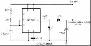
I've found a 555 circuit to invert voltage (Attach), Problem is it apparently drops a little voltage from the input. Can somebody please help me get around this, +14.5 Volts in I need -14.5Volts out for a few opamps . Many thanksEven the 555 will do the job
Attachments
Last edited:
stoppage - If you are just powering op amp(s) something like this +/-12Vdc output, 13.5-16.5Vdc input, DC-DC converter module would also work. $8.76 USD at Mouser (#580-NMA1512SC):
NMA1512SC Murata Power Solutions | Mouser
http://www.mouser.com/ds/2/281/kdc_nma-29224.pdf
or the same thing but with +/-15Vdc output (Mouser #580-NMA):
NMA1515SC Murata Power Solutions | Mouser
also at Farnell http://export.farnell.com/_/dp/1562184
You only get 42mA per rail with the +/-12Vddc output version or 33mA with the +/-15Vdc version, but if you are just powering a couple of op amps that may be enough. They have them in both SIP (on edge) and DIP (flatter) versions.
The switching frequency is up at 90kHz, above the audio band, but if you really want to get rid of any switching ripple you could use the +/-15Vdc output version then follow it with a LT1963A (positive) and LT3015 (negatvie) LDO voltage regulator set for +/-12Vdc, like dangus posted. The LDOs only need around 0.1V across them at those low currents. With +/15Vdc input from the DC-DC converter you could set them (they are adjustable) for up to +/14.9Vdc or so output if you wanted to take advantage of the full voltage swing available, or use the +/-12Vdc output version of the DC-DC converter and set the LDOs for +/-11.9Vdc output.
Last edited:
...or, for the same money, you can get just an isolated 15Vdc to 15Vdc converter to use for the negative rail, at twice the current capability (67mA), then follow that with a LT3015 if you want (part# NME1515SC):
NME1515SC Murata Power Solutions | Mouser
also at RS Components:
http://uk.rs-online.com/web/p/products/6895059/?cm_mmc=aff-_-uk-_-octopart-_-6895059
NME1515SC Murata Power Solutions | Mouser
also at RS Components:
http://uk.rs-online.com/web/p/products/6895059/?cm_mmc=aff-_-uk-_-octopart-_-6895059
Last edited:
You can use Schottky or germanium diodes in place of the 1N4001s to help minimize the voltage drops, and add regulators to provide ±10-11 volts for the op amps.I've found a 555 circuit to invert voltage (Attach), Problem is it apparently drops a little voltage from the input. Can somebody please help me get around this, +14.5 Volts in I need -14.5Volts out for a few opamps . Many thanks
Try this:
MC34063A design tool
Just tell it the input is 15 and the output is -18 (and say 100 mA, 100 mV p-p ripple, and 33 kHz). Then hit the Calculate button. (You can then regulate the -18 to -15, with a three-terminal regulator IC circuit.) You can tell it to switch at up to 42 kHz, which should give smaller inductor and output capacitor values.
The results will show something like:
Ct=688 pF
Ipk=463 mA
Rsc=0.648 Ohm
Lmin=521 uH
Co=155 uF
R1=5.6k R2=75k (17.99V)
and it will give something like the attached schematic.
Make sure you also try specifying 300 mA instead of 100 mA, for the output current. You can use a range of component values, in some places. Entering 300 instead of 100 mA gives, for example:
Ct=688 pF
Ipk=1389 mA
Rsc=0.216 Ohm
Lmin=174 uH
Co=465 uF
R1=5.6k R2=75k (17.99V)
The datasheet even has suggested PCB layouts:
https://www.sparkfun.com/datasheets/IC/MC34063A.pdf
And it's a nice, standard little 8-pin DIP part.
Cheers,
Tom
Attachments
Last edited:
...or, for the same money, you can get just an isolated 15Vdc to 15Vdc converter to use for the negative rail, at twice the current capability (67mA), then follow that with a LT3015 if you want (part# NME1515SC):
NME1515SC Murata Power Solutions | Mouser
also at RS Components:
Buy Isolated DC-DC Converters DC/DC converter,15Vin,15Vout 67mA 1W Murata Power Solutions NME1515SC online from RS for next day delivery.
I haven't been around here for a while, too many other committments, appologies and thank you all for your continued assistance, its a great place for information.
I have some questions on this device, I have a problem with the datasheet, perhaps you can help.
I have a +14.5 Volt supply, as I understand it this device has only one negative output...-15 Volt.
So for a TL072 (from the datasheet it has a Vcc of ±18 Volts) TL072 datasheet pdf datenblatt - STMicroelectronics - LOW NOISE J-FET DUAL OPERATIONAL AMPLIFIERS ::: ALLDATASHEET :::
I would then, as supply voltage have +14.5 and -15 Volts. Will this work?
- Status
- This old topic is closed. If you want to reopen this topic, contact a moderator using the "Report Post" button.
- Home
- Amplifiers
- Power Supplies
- 12 volt power supply