Pedro,
As JBL said, more fets, a bigger core (sometimes the same core can be used) and attention to the rectifiers and filtering I suppose it might work. Some adjusts in compensation network, snnubers and dead time might be necessary to improve efficiency and stability.
I designed a switchmode power supply very similar to Rod´s one, using SG3525 pwm controller and, using the same topology, with 3 MTP50N06 mosfets per phase it pumped out almost 1KW to the power amps! Lots of cooper on pcb´s SHORT tracks (it drains near 85A from the battery!!!) and a very careffuly layout are mandatory.
Saudações
Hi blmn!
Thanks 4 that!
When I have all done, I'll post here the schematics and the pcb layout!
With large tracks!! of course!
Translation to portuguese:
Obrigado por isso!
Quando estiver tudo feito, coloco aqui o esquema e o circuito impresso!
Com pistas bem largas, claro!
Cumprimentos
Thanks 4 that!
When I have all done, I'll post here the schematics and the pcb layout!
With large tracks!! of course!
Translation to portuguese:
Obrigado por isso!
Quando estiver tudo feito, coloco aqui o esquema e o circuito impresso!
Com pistas bem largas, claro!
Cumprimentos
Forgot this:
The layout of the amplifier:
The layout of the amplifier:
An externally hosted image should be here but it was not working when we last tested it.
audioPT said:Forgot this:
The layout of the amplifier:An externally hosted image should be here but it was not working when we last tested it.
Try to move your filter caps to the left and right of your transformer. this should help to reduce the trace lengths of your high current leads. This in turn will reduce total leakage inductance.
If you have a scope, great. If not, get one, get a good one... ...you'll need it.
There will be two critical things you will need to test for. Overvoltage on the switching devices due to fast turn off times in your switching transistors is one of them. To have any efficiency, you will want relativley low voltage fets (50 or 60 volts) because they have lower Rds-on resistances. But, any leakage inductance and fast switch times will kill your devices.
Also, you will need to watch dead time of your switching devices. If one of the devices is still on when the other turns off, you will cause an effective shorting on your transformer, thus inducing large current draws that may cause damage to the fets (otherwise known as cross conduction)
Keep in mind both of these are opposing problems, as the solution to one may be the cause of the other!
I'm sure we are all willing to offer help, if you are serous about the project. Keeps us updated on your progress! I personally would like to hear about it as you go.
-Dan
P.S. I have a pic of my supply in my introduction thread... ...if you're intrested. (Around 2Kw from 12 Volts)
JBL said:Hmm look like alot of capacitor for a switch mode power supply
Wonder what the loop response is like... ...fast or slow...
 It's only a first drawing...
Don´t cry Pedro,
You can use these quantity of capacitors in the 12V input with no problems, in large capacitance values. Use 105C temperature types.
And regarding output filtering, you can use many paralell low capacitance value low esr 105C types.
I think you are able to mantain your fine drawing, if you want to, but you have to take care of capacitors position and the others tips of dkempai") .
.
Saudações,
You can use these quantity of capacitors in the 12V input with no problems, in large capacitance values. Use 105C temperature types.
And regarding output filtering, you can use many paralell low capacitance value low esr 105C types.
I think you are able to mantain your fine drawing, if you want to, but you have to take care of capacitors position and the others tips of dkempai
. Saudações,
blmn said:
I designed a switchmode power supply very similar to Rod´s one, using SG3525 pwm controller and, using the same topology, with 3 MTP50N06 mosfets per phase it pumped out almost 1KW to the power amps! Lots of cooper on pcb´s SHORT tracks (it drains near 85A from the battery!!!) and a very careffuly layout are mandatory.
Saudações
LM3524 is a good controller. I assume that it is the same or similar to the SG3525? This should be a good place to start for controller.
As blmn has stated, lots of copper is good. It even helps if you can solder extra copper onto the board. I use 3/8" by 1/16" copper soldered onto etched traces (Maybe overkill, but better than burning up a trace).
Lots and lots of input caps will also be good, so don't fret about the drawing. Look into the FC series Panasonic caps, they're high frequency rated, and in my experience can dump energy quickly. The part I've listed is a 16 Volt, 3300uF cap. When I did the cost analysis, they gave the best performance for the price when paralleled. (I've used them more than half a dozen different
DC-DC designs, and have been very happy with them)
Digi-Key Part Number P10260-ND
Panasonic Part Number EEU-FC1C332
Transformer will be a little harder to come by. You will probably have to wind your own. I like torroids, but E-I cores are easier to wind.
-Dan
Yes,
The SG3524 is a good choice too. I don't remember exactly for now, but the output driver configurations are different.
I'd prefer toroids, even considering winding difficulties. After some time my fingers did not complain anymore
I'will try to photograph some of my prototypes to show you.
regards
The SG3524 is a good choice too. I don't remember exactly for now, but the output driver configurations are different.
I'd prefer toroids, even considering winding difficulties. After some time my fingers did not complain anymore
I'will try to photograph some of my prototypes to show you.
regards
3524 3525
Well, they were good in their day, but these designs are a little long in the tooth. I can see if you are really strapped for cash, maybe, but there are much, much quieter, greater current handling capability, efficient devices for not much more money, and, to boot, you have companies which put the design software right on their website for the newer chips.
For transformers -- go to international rectifier's site -- they have a tutorial -- as do a number of the companies which manufacturer cores.
http://members.tripod.com/valveaudio/schematics.htm might be useful
I'm in the planning part of making a 4x100rms (4x200rms @ 2 ohms) amp but since the biggest ferrite core I can get is 3.5cm there going to be one per amp. putting copper bar onto the tracks will help cut down the room needed for large tracks, spare windoing wire would do aswell.
I'm in the planning part of making a 4x100rms (4x200rms @ 2 ohms) amp but since the biggest ferrite core I can get is 3.5cm there going to be one per amp. putting copper bar onto the tracks will help cut down the room needed for large tracks, spare windoing wire would do aswell.
The SG3524 or SG3525 aren't right for this
these two chips are voltage-mode controllers, that is, the error amplifier senses the difference from reference at Vout and adjusts the duty cycle to reflect a change in input voltage or output current.<p> the problem with a push-pull design is that if there is an imbalance between the two transistors and one pulls more current than the other the transformer will quickly move into saturation, causing failure of the switching devices. This is more a problem with bipolar devices than MOSFET's, but a problem nonetheless. There are current mode controller chips which do the balancing and avoid (somewhat) this problem.
these two chips are voltage-mode controllers, that is, the error amplifier senses the difference from reference at Vout and adjusts the duty cycle to reflect a change in input voltage or output current.<p> the problem with a push-pull design is that if there is an imbalance between the two transistors and one pulls more current than the other the transformer will quickly move into saturation, causing failure of the switching devices. This is more a problem with bipolar devices than MOSFET's, but a problem nonetheless. There are current mode controller chips which do the balancing and avoid (somewhat) this problem.
Re: The SG3524 or SG3525 aren't right for this
jackinnj,
The 3524 has current mode as well as voltage mode. With push pull topology, you want voltage mode control, as the current drawn is a function of the gain of the transformer and the load impedance. This is a standard low voltage input SMPS scheme. Most car power amplifiers do not even care about the current. They don't measure it, since any sampling resistors would be expensive, and would waste too much power. Voltage mode only is the standard automotive amp PSU's.
Also, the transformer will not saturate because of an imbalance in the transistors. Even with an imbalance in transformer windings, this will not be a problem. The controller will accomidate by changing the pulse width of that particular power switch. (Maybe more heat will be generated, but probably less than 10% difference).
Saturation of the transformer will occur if the frequency is too low for the number of turns on the primary winding. Unlike inductor type SMPS supplies which rely on collapsing magnet field to generate output voltages, a push pull topology uses transformer coupling to convert power. As long as the frequency is high enough, you cannot saturate it. This is much like a standard linear supply for line voltages, except the flux waveform RMS value is changed for regulation.
Push-pull is the only topology that will handle large power levels at 12volt input. There is no other way.
fr0st,
If you are using a donut shaped core, you may be able to stack them together, and use them as one transformer. (This is common for very very large supplies).
The other option would be to use two individual sets of power magnetics and electronics. In this case you could use only one controller and two individual sets of transistors, diodes, and transformers in parallel. You could also design it to add as many stages as you could ever want. Sort of like the hot swap supplies often used in telcom apps.
Just a thought, if you have a 400W supply and enough caps, you could do 400W avg at 20Hz... ...you wouldn't need a 800W supply for 400W.
-Dan
jackinnj said:these two chips are voltage-mode controllers, that is, the error amplifier senses the difference from reference at Vout and adjusts the duty cycle to reflect a change in input voltage or output current. <p> the problem with a push-pull design is that if there is an imbalance between the two transistors and one pulls more current than the other the transformer will quickly move into saturation, causing failure of the switching devices. This is more a problem with bipolar devices than MOSFET's, but a problem nonetheless. There are current mode controller chips which do the balancing and avoid (somewhat) this problem.
jackinnj,
The 3524 has current mode as well as voltage mode. With push pull topology, you want voltage mode control, as the current drawn is a function of the gain of the transformer and the load impedance. This is a standard low voltage input SMPS scheme. Most car power amplifiers do not even care about the current. They don't measure it, since any sampling resistors would be expensive, and would waste too much power. Voltage mode only is the standard automotive amp PSU's.
Also, the transformer will not saturate because of an imbalance in the transistors. Even with an imbalance in transformer windings, this will not be a problem. The controller will accomidate by changing the pulse width of that particular power switch. (Maybe more heat will be generated, but probably less than 10% difference).
Saturation of the transformer will occur if the frequency is too low for the number of turns on the primary winding. Unlike inductor type SMPS supplies which rely on collapsing magnet field to generate output voltages, a push pull topology uses transformer coupling to convert power. As long as the frequency is high enough, you cannot saturate it. This is much like a standard linear supply for line voltages, except the flux waveform RMS value is changed for regulation.
Push-pull is the only topology that will handle large power levels at 12volt input. There is no other way.
fr0st,
If you are using a donut shaped core, you may be able to stack them together, and use them as one transformer. (This is common for very very large supplies).
The other option would be to use two individual sets of power magnetics and electronics. In this case you could use only one controller and two individual sets of transistors, diodes, and transformers in parallel. You could also design it to add as many stages as you could ever want. Sort of like the hot swap supplies often used in telcom apps.
Just a thought, if you have a 400W supply and enough caps, you could do 400W avg at 20Hz... ...you wouldn't need a 800W supply for 400W.
-Dan
dkemppai,
There is another possibility for 12V smps, the full bridge configuration. There is an article in Elektor Electronics (I don't remember the number) about an amplifier using this configuration. Half bridge might work too, BUT, these two alternatives are very complex (if you compare them with the push-pull type) and the push-pull works very well in this case. I have made many of these voltage mode SMPS for power amps and I don't remember of any problem with imbalance, since 1995.
About this question, Pressman - Switchmode Power Supply design - 2nd Edition - ISBN 0-07-052236-7 - pages 43 to 45 - gives a good explanation for the good tolerance of flux imbalances of mosfets in push pull designs.
As you've stated, as far as I know, 99.99% of commercial amps are voltage mode push pull models. There are some new mosfets with a current "sensor" terminal, but, I don't know very much about them.
Have you asked about the maximum power for a given core, in another thread? I'm using the formulae at the McLyman's book called Design Magnetic Components for High Frequency dc-dc Converters - ISBN 1-883107-00-8 - and it works very well.
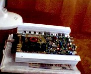
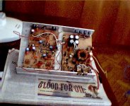
I tried to take some shots of my prototypes and I got these pics below. I have just one cheap webcam, so the images are very bad quality.
One is of a pre commercial prototype of a 200w x 2 at 2ohms amp using the SG3525 IC. The other three are of an hand made heatsink and pcb for a 75w x 2 at 2 ohms pwr amp. A very simple (and bad) power amp, just to test the smps.
Regards
There is another possibility for 12V smps, the full bridge configuration. There is an article in Elektor Electronics (I don't remember the number) about an amplifier using this configuration. Half bridge might work too, BUT, these two alternatives are very complex (if you compare them with the push-pull type) and the push-pull works very well in this case. I have made many of these voltage mode SMPS for power amps and I don't remember of any problem with imbalance, since 1995.
About this question, Pressman - Switchmode Power Supply design - 2nd Edition - ISBN 0-07-052236-7 - pages 43 to 45 - gives a good explanation for the good tolerance of flux imbalances of mosfets in push pull designs.
As you've stated, as far as I know, 99.99% of commercial amps are voltage mode push pull models. There are some new mosfets with a current "sensor" terminal, but, I don't know very much about them.
Have you asked about the maximum power for a given core, in another thread? I'm using the formulae at the McLyman's book called Design Magnetic Components for High Frequency dc-dc Converters - ISBN 1-883107-00-8 - and it works very well.
I tried to take some shots of my prototypes and I got these pics below. I have just one cheap webcam, so the images are very bad quality.
One is of a pre commercial prototype of a 200w x 2 at 2ohms amp using the SG3525 IC. The other three are of an hand made heatsink and pcb for a 75w x 2 at 2 ohms pwr amp. A very simple (and bad) power amp, just to test the smps.
Regards
Attachments
- Status
- This old topic is closed. If you want to reopen this topic, contact a moderator using the "Report Post" button.
- Home
- Amplifiers
- Solid State
- 12 to 35-0-35V