Blaxshep,
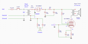
1. You still forgot to ground one end of the output transformer secondary.
What if the primary and secondary short to each other, it is not likely, but neither is a "successful lightning strike" directly to my body. The result can be the same.
2. The only significant current leakage to the chassis that I see during normal operation is from the power transformer primary to its laminations, and the output transformer primary to its laminations.
Why use a 100 Ohm resistor, and a 1 uF there, just directly connect the chassis to the other ground connections.
3. Ground loops are pernicious. For example, make a direct connection from the bottom (-) of the 33uF cap and the bottom (-) of the 100uF cap to the bottom of the power transformer secondary. The impulsive current could cause a magnetic field that will cause interference.
Keep that "aperture" short, and away from other circuitry.
Those kinds of things are not something that shows up on schematics.
But it is one cause of hum that so many on this web are experiencing.
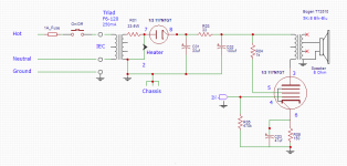
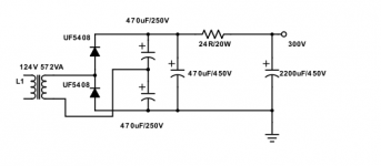
Ahhh, now it is safe, as long as no fingers touch anything, and as long as no parts burn up (have the proper ratings of voltage, power, etc).
If the pentode dies, the voltage ratings of the 33uF and 100uF need to be more than 1.414 times the secondary rms voltage (and do not forget to account for the primary voltage rating versus your actual maximum power line voltage, that will cause the secondary rms to go up proportional too).
If the pentode dies, the voltage ratings of the 33uF and 100uF need to be more than 1.414 times the secondary rms voltage (and do not forget to account for the primary voltage rating versus your actual maximum power line voltage, that will cause the secondary rms to go up proportional too).
I have this General Radio oscillator (1000Hz, apparently made for use with GR Z-Y bridges), which I thought it was bizarre when I looked inside (or did I look up the schematic on the Internet?) and saw that it uses a tube heater run right off the power line (!), as well as much other circuitry likewise run off the power line. At least the chassis is grounded, and the output is transformer-isolated from the main circuitry (thus I think it's within the rules of posting here):
General Radio 1214-A Unit Oscillator | Steve's Web Junkyard | Steve Byan
If you want to make a "one tube amp" I recall there was one using three gain stages in a Compactron tube (with likely a reasonable 12V filament) somewhere in this long guitar-amp thread:
The Hundred-Buck Amp Challenge
General Radio 1214-A Unit Oscillator | Steve's Web Junkyard | Steve Byan
That is a really good idea, the 117N7 does not amplify the incoming signal very much on it's own (Low Mu), but I was kinda liking the idea of a one tube amp and I thought it would be interesting to see just how this cheap tube sounds.
If you want to make a "one tube amp" I recall there was one using three gain stages in a Compactron tube (with likely a reasonable 12V filament) somewhere in this long guitar-amp thread:
The Hundred-Buck Amp Challenge
Safety:
The GR 1214A has several safety features:
The power input is 3 wire with ground.
The shield / chassis connects to the ground of the power input.
The output transformer shield is grounded to the ground of the power input.
The shield isolates the ‘hot’ primary from the floating secondary.
This is the isolation transformer, it is not necessary to have a power transformer.
Both Neutral and Hot are fused for US, and also for floating power systems of 115V 40-60 Hz..
The above features, plus a properly grounded power outlet, and a proper 3 wire power cord makes this generator safe.
Safe!
Unusually high voltage output:
I expect that the output power rating of the GR 1214A is for rms power, not peak power.
The output of 0.2 Watts rms into 8k Ohms is 56.56Vrms.
56.56Vrms is 80V peak, 160V peak to peak.
With 50V/division on the 465 scope, it looks like you have 80V peak, and 160V peak to peak.
You are not even loading the output with 8k Ohms in parallel with the 10k Ohm potentiometer, so you ought to be getting more than 80V Peak, etc. That is because the pentode is a current source, a high impedance, and not loading the output terminals with 8k Ohms gives a higher voltage out.
Excess Voltage output solved!
Last edited:
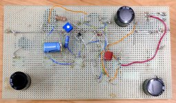
Thanks very much for the lesson on safe circuits. I have been using 160V caps in my breadboard sounds like I should use the 250V caps I have for the real thing.
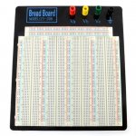
When you say breadboard, what are you using? It's not one of these is it?
http://www.ladyada.net/images/parts/breadboard-half.jpg
Because those shouldn't have anything over 48v on them.
I have been using 160V caps in my breadboard sounds like I should use the 250V caps I have for the real thing.
Anything running from rectified isolation transformer should have at least 200 volt caps in it, but 250 volt caps are more common, so that's what I use.
Most isolation transformers are not 1:1. They have a slight step up ratio so that they will be 1:1 at full rated load. The popular Triad N-68X can put out over 140 volts with a light load on today's 120+ volt line voltage. I have one in a little guitar amp which pulls 100 mA for the heaters, and 40 to 80 mA for B+ depending on how hard you hammer it. The B+ is about 170 volts at idle and 165 cranked......too much for 160 volt caps. It has 250 volt caps.
I use 400 volt caps in circuits that run a voltage doubler from an isolation transformer. The B+ runs from 340 to 355 volts depending on load, again too much for common 350 volt caps.
Running the isolation transformer backwards, plugging the single secondary into the wall, and wiring the primaries in series for 240 VCT does result in a lower B+. I still use the higher voltage caps.
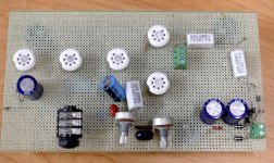
When you say breadboard, what are you using? It's not one of these is it?
I usually make a PCB, or do something like this:
I've seen a few used in interesting ways by people who should have known better..
UH,.....who me?....NO, I know better than post pictures of some of my experiments.
Attachments
<snip>
UH,.....who me?....NO, I know better than post pictures of some of my experiments.
You are no doubt one of the most fearless experimenters I know, and also without question the one who is most safety conscious. I never worry about you or the advice you give.

I sometimes think what would tubelab do before proceeding with an experiment. I definitely don't have nerves of iron though, so mine are comparatively tame..
I use 250V caps in the doubler (in place of diodes in the normal bridge circuit), and 450V at the exit. Is that what you do? On 120V the peak is only 170V, right?I use 400 volt caps in circuits that run a voltage doubler from an isolation transformer. The B+ runs from 340 to 355 volts depending on load, again too much for common 350 volt caps.
Attachments
On 120V the peak is only 170V, right?
Correct. The line voltage here runs anywhere from 122 to 128 volts and dances all over the place during the winter when everybody's electric heat is cycling. The pole transformer is right outside our house such that the service drop ia maybe 30 feet long. We get the most voltage.
yes, I will use 250 volt caps for each individual stage and a 400 volt cap for the output. 400 volt caps are the common voltage used in SMPS and PC power supplies, so they are the most common voltage on the surplus market.
You are no doubt one of the most fearless experimenters I know
I have grown more conservative as I get older. Too many things have blown up in my past that caused me no major grief. Looking back any one of those could have ended very badly.
I have exceeded the common sense voltage on the little white breadboards a few times. I keep several empty rows between HV rows and use a power supply that will not cause a major bang even when shorted out at full voltage.
When I was in a technical high school (1967 - 1970) we had some large versions of these boards. They were about 12 X 18 inches, made of clear plastic and designed for vacuum tube breadboarding. They were called DeVry boards after the tech school of the same name. I can not find any info on these now, but it would be cool to have a few. There were also plug in tube sockets in 7, 8 and 9 pin flavors.
When your'e about to flip the switch on anything new, or containing serious amounts of stored energy, it is wise to consider all the possible failure modes, and how to handle them before flipping the switch.
I have been working on a DIY SMPS for vacuum tube power. I think it will get tested outside at the end of a long extension cord for its first connection to line voltage.
If you are feeding that thing 250 volts make sure that metal plate is grounded. I have the same plastic pieces, but mounted them myself on a piece of PC board with a .020 sheet of Lexan between the plastic parts and the PC board which is connected to earth ground and power supply negative.
I wouldn't put that much voltage between adjacent strips either. I use an old Knight Kit vacuum tube regulated power supply that will not blow much stuff up even when shorted out.
I wouldn't put that much voltage between adjacent strips either. I use an old Knight Kit vacuum tube regulated power supply that will not blow much stuff up even when shorted out.
- Status
- This old topic is closed. If you want to reopen this topic, contact a moderator using the "Report Post" button.
- Home
- Amplifiers
- Tubes / Valves
- 117v heater tube 117n7