Hi! Mile
I have changed all the small transistors then i got 2.8mV dc offset when input is grounded but when signal is given its changing btw -ve and +ve that means its not maintaining constant at 2.8mV is this normal ??????
Is this on the output? If it is-that is more than 0k!
Thanks very much about your support!Nice pcb, use 2SA970 and 2SC2240 instead 2N5401 and 2N5551.
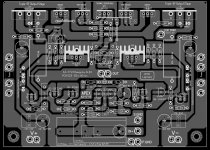
Thanhs Sir! Before I smell smoke...viktor1986 has noticed a mistake in a pcb-design: the base of the 2SC5200 is connected to a base 2SC4793,instead to it´s emitor. The lines to B and E of 2SC4793 have switched places,that should be changed.
That is what i have noticed after viktor´s warning,maybe he has seen something more,i don´t know. As far as i have seen that would be the only mistake done here...
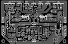
") I share my update corrected PCB here after, with two option: original and alternative (2SA970 -2SC2240 replace 2N5401 - 2N5551) for anyone like it.
I share my update corrected PCB here after, with two option: original and alternative (2SA970 -2SC2240 replace 2N5401 - 2N5551) for anyone like it.Attachments
Yes Sir! I will try again & check in datasheet to refix it. Thanks again!Viktor noticed one more thing-mje and bd are with wrong pinout,it is reversed from real. Otherwise,pcb is very very nice and comact!
Hi! Mile
I have changed all the small transistors then i got 2.8mV dc offset when input is grounded but when signal is given its changing btw -ve and +ve that means its not maintaining constant at 2.8mV is this normal ??????
No you have done a mistake somewhere recheck it again
offset is ok but that should be constant enough whether there is input signal or not
This leads to distortion in LF and slightly may be in HF
Last edited:
pre-drivers have virtually no effect on output offset. Except if you blow up one of the pre-drivers. That would affect the output offset.Is there any chance of getting dcoffset with unmatched pre-drivers
Yeah. Thanks Vitor too! I checked datasheet of TO-92, most BCxxx and 2Nxxxx is C-B-E, or E-B-C (simple reverser side). And most 2S Japanese transistors is E-C-B. So, I try first to build with 2S and BC transistor. If I have more time, I'll repair my mistaken PCB posted. Today, I check carefully one by one component and hope it no more errors. Sorry because my limited English, hard to describe my thinking to be write understandability (I only read is better).viktor also said that you should pay attention to a TO92 transistor pin-outs too. Man,viktor said soo much...
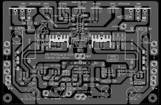
I add variable input capacitor, a couple 0.1uF bypass in parrapell with decoupler el-cap pair, multiturn trimmer for higher quality option. And resistor 2.2k // with bias adjusment trimmer set for safer.
Attachments
can somebody tell whether the polarity of c6 in ax-14 is correct?
my opinion is negative of C6 - negative feedback dc isolation connect with ground (better is same input audio ground) in all of shematic I saw. In my PCB, I make that too. However, waiting for an answer' author is best.
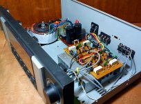
Hi Mr. MIle... This is my AX 14 stereo.... the sound is very good... 50 volt dc.. dc ofset 3.2 mv and 4.8mv.. seting bias at 15mv.... thanks for your schematic....sory for my english...
Is your DC offset is stable while playing?
dc ofset
the dc ofset not stabel while playing...is it normal sir?Is your DC offset is stable while playing?
- Home
- Amplifiers
- Solid State
- 100W Ultimate Fidelity Amplifier