you have some strange reaction to my words (“if you don’t believe me ... don’t ask in a personal message.”) I only asked to explain that I didn’t understand that was all. maybe forgot to say thank you for the answers and the improved circuit at the same time ... for this I apologize and say a huge thank you. only so and nothing bad, no mistrust!
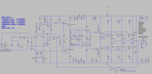
Reduce distortion a bit.I modified AX20
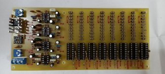
Attachments
BIMO, Just super !! Thank you!!
Again I want to ask, I hope you will not be offended in any way .-)
It seems to me, that R32-R33 is usually set at 22-47 Ohm, and you have 270 Ohm. So 270 is better than 47?
Also Q1 and Q2 can be exchanged for bс560 for more versatility?
Again I want to ask, I hope you will not be offended in any way .-)
It seems to me, that R32-R33 is usually set at 22-47 Ohm, and you have 270 Ohm. So 270 is better than 47?
Also Q1 and Q2 can be exchanged for bс560 for more versatility?
Resistor's emitter of LTP influence of the slew rate, noise, and linearity. It is depend on trade-off of the designer. In the amplifier, noise less consider than linearity. And in this topology because LTP loading with current mirror make gain very high, so we can use high value of the resistor to get higher slew rate.BIMO, Just super !! Thank you!!
Again I want to ask, I hope you will not be offended in any way .-)
It seems to me, that R32-R33 is usually set at 22-47 Ohm, and you have 270 Ohm. So 270 is better than 47?
Also Q1 and Q2 can be exchanged for bс560 for more versatility?
Q1 and Q2 can use BC560C but VCE in the limit of their specification. You can use any transistor with high hFE but watch-out the SOA (Safe Operating Area) of the transistor.
Slew rate is capability of the amplifier to change the output voltage in specific time or voltage changing divided by time changing = dV/dT.And such questions have arisen. What is the slew rate and phase margin?
Phase margin and gain margin is criteria of stability of amplifier in small signal analyses. The stability of the amplifier in small signal analyses was defined by Nyquist.
Amplifier power supply + -46v. Mental calculation: 200 watts into 4 ohms. - maximum power.
and your simulator gives out 308 ... that's another question ...
In my simulator I used arbitrary level to calculate THD. Usually I use level close to clipping. It is not the maximum power. It should be in 2 Ohm not 4 ohm.
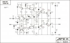
Thank you, bimo. Here friends repeated your scheme, said that there could be a generation problem at 17 MHz. Here is the picture below. And they say this option is better and easier. only С11 it is necessary to change to 15pF in the diagram below
PS^ tracking fieldworkers in the input DC- reduce distortion well, but if there is no desire to put them - it is not necessary.
PS^ tracking fieldworkers in the input DC- reduce distortion well, but if there is no desire to put them - it is not necessary.
Attachments
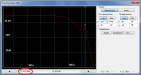
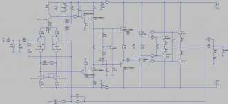
Maybe he used different models of the transistor. In my simulation there is no peak at 17 MHz.Thank you, bimo. Here friends repeated your scheme, said that there could be a generation problem at 17 MHz. Here is the picture below. And they say this option is better and easier. only С11 it is necessary to change to 15pF in the diagram below
PS^ tracking fieldworkers in the input DC- reduce distortion well, but if there is no desire to put them - it is not necessary.
Hi, Mr. Astaro. Can I use the Soviet assembly as J1, J2 - KP504HT1 ? PostThank you, bimo. Here friends repeated your scheme, said that there could be a generation problem at 17 MHz. Here is the picture below. And they say this option is better and easier. only С11 it is necessary to change to 15pF in the diagram below
PS^ tracking fieldworkers in the input DC- reduce distortion well, but if there is no desire to put them - it is not necessary.
Last edited:
- Home
- Amplifiers
- Solid State
- 100W Ultimate Fidelity Amplifier