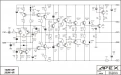
What might be a better "high voltage" transistor to exchange in the AX-14 for the 5200/1943 typical outputs?
I am considering one of these:
2SC5200/1943 are 150W parts
MJL or W 1302/3281 are 200W parts
MJL 4302/4281 are 230W parts
If I want to run this amp at +/-65Vdc, which would be better choice with 2 pairs of outputs? 2sc5200/1943, MJ(L or W)3281/1302 or MJL4281/4302?
I am considering one of these:
2SC5200/1943 are 150W parts
MJL or W 1302/3281 are 200W parts
MJL 4302/4281 are 230W parts
If I want to run this amp at +/-65Vdc, which would be better choice with 2 pairs of outputs? 2sc5200/1943, MJ(L or W)3281/1302 or MJL4281/4302?
What might be a better "high voltage" transistor to exchange in the AX-14 for the 5200/1943 typical outputs?
I am considering one of these:
2SC5200/1943 are 150W parts
MJL or W 1302/3281 are 200W parts
MJL 4302/4281 are 230W parts
If I want to run this amp at +/-65Vdc, which would be better choice with 2 pairs of outputs? 2sc5200/1943, MJ(L or W)3281/1302 or MJL4281/4302?
MJL4302/4281 would be best but I would not go lower that 8 ohms with that high of rails and only two pair.
MJL4302/4281 would be best but I would not go lower that 8 ohms with that high of rails and only two pair.
Why would I buy those, if I can run 4-ohm loads at +/-55Vdc with cheaper 2sc5200/1943? Was hoping I could get more SOA at +/-65Vdc rails with a more robust transistor. Is that not how it works?
Why would I buy those, if I can run 4-ohm loads at +/-55Vdc with cheaper 2sc5200/1943? Was hoping I could get more SOA at +/-65Vdc rails with a more robust transistor. Is that not how it works?
IMO you are pushing it running 4 ohm at +-55V. If you are getting away with it fine. You asked about going to +-65V. I think that is pushing it but I am probably not the best guys to answer this. There are plenty of engineers around here that can give much better advice than me. I bow out.
Maybe I didn’t ask correctly - didn’t mean to offend, or come across as unappreciative. I know you have built a lot of amps.
I’m asking from ignorance (noob) and trying to understand why 4-ohm loads seem to be acceptable from some people and then others (not just you) say to buy more robust transistors or add an additional pair.
Again noob thinking - but 10V doesn’t seem like a big difference for a 200-250V part that can dissipate 150-200W.
I know this is where my ignorance comes in because I don’t know how to calculate a SOA for an output transistor, but I also don’t run my amps anywhere near there maximums either.
So that’s why I’m asking, not to confront, rather to learn the “why” that a different part is a better choice.
Maybe I didn’t ask correctly - didn’t mean to offend, or come across as unappreciative. I know you have built a lot of amps.
I’m asking from ignorance (noob) and trying to understand why 4-ohm loads seem to be acceptable from some people and then others (not just you) say to buy more robust transistors or add an additional pair.
Again noob thinking - but 10V doesn’t seem like a big difference for a 200-250V part that can dissipate 150-200W.
I know this is where my ignorance comes in because I don’t know how to calculate a SOA for an output transistor, but I also don’t run my amps anywhere near there maximums either.
So that’s why I’m asking, not to confront, rather to learn the “why” that a different part is a better choice.
Others can correct me if I'm wrong but the outputs see full rail to rail so adding +-10V is 20V P-P. If you are not running anywhere near full power, why jump up in voltage? Just change to MJL4302/4821 and be happy. You will likely never notice the higher rails and your transistors will thank you.
I don’t have two PSUs, mine is +/-65Vdc and was trying to avoid buying another transformer.
I mention 55V rails as what was “recommended” on YouTube and throughout this thread, sorry if that was confusing.
The other reason I ask, is because I already bought some 2sa5200/1943s and I’m second guessing that now.
I guess I need to figure out if transistors or transformer is the better upgrade option.
I understand where you are coming from. When I first started building DIY amps I bought a big transformer that was too big for the amp I wanted to build. That caused me to build a Leach Superamp so I could us it.
As and example, the Honey Badger recommends +-60V and it has three pair of outputs. I would suggest if you want to use that PSU that you already have that you use at least 3 pairs of outputs. The AX14 will easily handle that. I built an AX14 as an IPS and put it in front of a Slewmaster OPS and it was stellar.
As and example, the Honey Badger recommends +-60V and it has three pair of outputs. I would suggest if you want to use that PSU that you already have that you use at least 3 pairs of outputs. The AX14 will easily handle that. I built an AX14 as an IPS and put it in front of a Slewmaster OPS and it was stellar.
Attachments
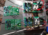
I know I ask a lot of questions to the forum and I never posted any pictures of my DIY, just out of curiosity to hear the sound, I'm assembling apex AX 11 and AX11 layout by Bimo / Prasi, the AX 20 because in the multisim simulation the AX20 was perfect, I'm riding SR150 too, I will still record SR200 and SR250. All this to put an end to the curiosity of what the sound is like. Together in the apex photo ON / OFF, soft start, PSU preamp ZY18 and PRO stereo.
I thank Mile and colleagues on the forum for the layouts.
I thank Mile and colleagues on the forum for the layouts.
Attachments
I know I ask a lot of questions to the forum and I never posted any pictures of my DIY, just out of curiosity to hear the sound, I'm assembling apex AX 11 and AX11 layout by Bimo / Prasi, the AX 20 because in the multisim simulation the AX20 was perfect, I'm riding SR150 too, I will still record SR200 and SR250. All this to put an end to the curiosity of what the sound is like. Together in the apex photo ON / OFF, soft start, PSU preamp ZY18 and PRO stereo.
I thank Mile and colleagues on the forum for the layouts.
hi clpk ,what method do you use for tinning your pcb?
What might be a better "high voltage" transistor to exchange in the AX-14 for the 5200/1943 typical outputs?
I am considering one of these:
2SC5200/1943 are 150W parts
MJL or W 1302/3281 are 200W parts
MJL 4302/4281 are 230W parts
If I want to run this amp at +/-65Vdc, which would be better choice with 2 pairs of outputs? 2sc5200/1943, MJ(L or W)3281/1302 or MJL4281/4302?
Hi you should you this, at list 3 powers negative rail and 3 powers on positive rail.
Attachments
"I built an AX14 as an IPS and put it in front of a Slewmaster OPS and it was stellar."
Hallo Terry, how does the front end of the AX14 compares to the other original front ends of the Slewmaster, eg Knd,Nad and the others ?
Regards
Jan
Hi Jan,
As I recall, it measured very well and compared nicely to the others.
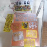
hi clpk ,what method do you use for tinning your pcb?
I spread a thin layer of soldering resin on the PCB so that the tin can spread on the copper and then melt the tin with the soldering iron and spread on the copper with the soldering iron. Take care not to overheat the copper, it can detach the copper from the plate.
Greetings
I spread a thin layer of soldering resin on the PCB so that the tin can spread on the copper and then melt the tin with the soldering iron and spread on the copper with the soldering iron. Take care not to overheat the copper, it can detach the copper from the plate.
Greetings
greetings too and thanks for the quick reply , the method takes a lot of time , i wish there was an easy quick diy method , maybe applying varnish will help the copper not to corrode

greetings too and thanks for the quick reply , the method takes a lot of time , i wish there was an easy quick diy method , maybe applying varnish will help the copper not to corrode
Ok, for DIY varnish is also good. I tinned the plate to make the tracks thicker, resistant to high current.
Greetings
- Home
- Amplifiers
- Solid State
- 100W Ultimate Fidelity Amplifier