Very nice!!. From where did you take spk out connection?
reg
Prasi
just saw it...dont bother...
Very nice!!. From where did you take spk out connection?
reg
Prasi
just saw it...dont bother...
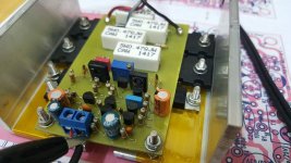
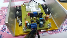
Thanks... speaker connected on the (OUT)
Thanks... speaker connected on the (OUT)
very nice! where is pgnd connected?
very nice! where is pgnd connected?
Input GND should connect to star GND and PSU or Power GND.
Last edited:
Input GND should connect to star GND and PSU or Power GND.
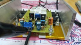
yes. very elegant design. can you educate a newbie on your ground connections? does signal ground connect directly to star ground...then rca input ground will also connect directly to star ground? thanks.
yes. very elegant design. can you educate a newbie on your ground connections? does signal ground connect directly to star ground...then rca input ground will also connect directly to star ground? thanks.
ok. i see the alligator clip now. im guessing that goes to star ground. thanks.
regards,
freeman
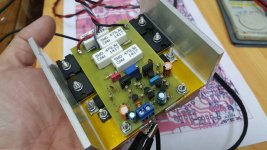
Beautiful!
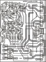
Post the pcb here.
I guess ,you will see guys to follow you.
")
Here's the file for you to DIY.
https://www.dropbox.com/s/m8qma092ijh7vuu/AX-14 Ver. 2.0.rar?dl=0
Regards,
https://www.dropbox.com/s/m8qma092ijh7vuu/AX-14 Ver. 2.0.rar?dl=0
Regards,
very nice! where is pgnd connected?
Nice work,
Regards
Very beautiful! I think I need a new AX14...
Regards
Olaf
yes. very elegant design. can you educate a newbie on your ground connections? does signal ground connect directly to star ground...then rca input ground will also connect directly to star ground? thanks.
Beautiful!
Post the pcb here.
I guess ,you will see guys to follow you.
Thanks everyone i'm glad you like it..
Regards,
Input GND should connect to star GND and PSU or Power GND.
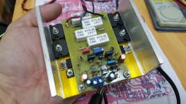
Hi Wiljj78,
Nice layout.
Mr. Miles's schematics/ layouts always have separate power ground and signal ground. and i/p ground has to be connected separately to PSU star ground.
Have you run into any hum issues with your layout?
reg
Prasi
example attached...
Attachments
Last edited:
Hi Wiljj78,
Nice layout.
Mr. Miles's schematics/ layouts always have separate power ground and signal ground. and i/p ground has to be connected separately to PSU star ground.
Have you run into any hum issues with your layout?
reg
Prasi
example attached...
Not at all... The amp is playing crystal clear and dead silent..
Not at all... The amp is playing crystal clear and dead silent..
ok. great!
reg
prasi
There is FX8
This amplifier almost escaped my attention
.Mr. Miles, is there a layout for this amp? Else, I will make one and share here with sk1058 and sj162. I think it will be a simple and good amp
.reg
prasi
Mr. Miles I would love to ask a favour to you
I have a symmetrical amplifier similar to the VSSA (actually the idea was taken from my amplifier) Several dyers wrote these amplifier inspired Lazy Cat amp and others to.. I'm not sure but really does not mater.
My amplifier uses Darlington power transistors TIP142 & TIP147 or BDW83C & 84C
I do love the amplifier a lot, to me it is my darling but it has some thermal instability (thermal drift) when warms up the amplifier bias rise with until self destruction of course based on the size of the heatsink and the starting bias.
I tried so many think to stabilise it but really not much success.
Would you please take a look if you can come up with some idea..
Thank you in advance.
I do not post the circuit here for now, it would create a confusion to those who build your well designed amps, preamps etc.
Greetings
Hi Gaborbela, Do look back at your original thread. I did try your circuit with bipolar output and Lat FET outputs. I reported the results there. The bipolar with stable bias was also tried and it worked well. An additional resistor was used in the bias circuit. Go back to the thread ! Stable at 100mA bias ! However it didn't need that much bias to sound very good.
Very good sound from that circuit. Lat FET seemed slightly light weight compared to the bipolar's but had a slightly crisper HF. Not a large difference but if you listened very carefully with a good recording , you can hear it.
I started on a board with higher supply rails but haven't yet got round to it. I think it sounds better than several other amps I have around here.
Mr. Miles I would love to ask a favour to you
I have a symmetrical amplifier similar to the VSSA (actually the idea was taken from my amplifier) Several dyers wrote these amplifier inspired Lazy Cat amp and others to.. I'm not sure but really does not mater.
My amplifier uses Darlington power transistors TIP142 & TIP147 or BDW83C & 84C
I do love the amplifier a lot, to me it is my darling but it has some thermal instability (thermal drift) when warms up the amplifier bias rise with until self destruction of course based on the size of the heatsink and the starting bias.
I tried so many think to stabilise it but really not much success.
Would you please take a look if you can come up with some idea..
Thank you in advance.
I do not post the circuit here for now, it would create a confusion to those who build your well designed amps, preamps etc.
Greetings
Do you have a link for that amp?
- Home
- Amplifiers
- Solid State
- 100W Ultimate Fidelity Amplifier