I sat down to try drawing a layout for the Music Fidelity PSU and realized that it is almost exactly the ESP P05C less one pair of filter caps. The P05 C should be better because of the added filter and CRC.
Hi Mile,
I don't understand this one. Looks like you are throwing away 18V in a 15v PSU. Is this really better than the ESP P05?
http://sound.westhost.com/p05c-f1.gif
Thanks, Terry
Simple Preamp PSU
Attached Thumbnails
100W Ultimate Fidelity Amplifier-apex-2x18v-aclass-psu.jpg 100W Ultimate Fidelity Amplifier-apex-18vdc-shunt-regulator-gray.jpg
Hi Mile,
I don't understand this one. Looks like you are throwing away 18V in a 15v PSU. Is this really better than the ESP P05?
http://sound.westhost.com/p05c-f1.gif
Thanks, Terry
I sat down to try drawing a layout for the Music Fidelity PSU and realized that it is almost exactly the ESP P05C less one pair of filter caps. The P05 C should be better because of the added filter and CRC.
Hi Mile,
I don't understand this one. Looks like you are throwing away 18V in a 15v PSU. Is this really better than the ESP P05?
http://sound.westhost.com/p05c-f1.gif
Thanks, Terry
I made layout PCB for simple regulator like this: https://anistardi.wordpress.com/2015/12/01/15v-dual-power-supply/
I made layout PCB for simple regulator like this: https://anistardi.wordpress.com/2015/12/01/15v-dual-power-supply/
Hi Bimo,
Your circuit looks to be the same as the P05. What makes yours superior?
I sat down to try drawing a layout for the Music Fidelity PSU and realized that it is almost exactly the ESP P05C less one pair of filter caps. The P05 C should be better because of the added filter and CRC.
Hi Mile,
I don't understand this one. Looks like you are throwing away 18V in a 15v PSU. Is this really better than the ESP P05?
http://sound.westhost.com/p05c-f1.gif
Thanks, Terry
Mile's design is a class A shunt regulator. They are normally much quieter than IC based regulators. You will notice more of a difference in sound using these designs than you would switching to LM317/337 designs.
Mile's design is a class A shunt regulator. They are normally much quieter than IC based regulators. You will notice more of a difference in sound using these designs than you would switching to LM317/337 designs.
Hi Jeff,
So you believe the difference is audible and worth throwng away more than half the voltage?
Voltage is cheap, current is what costs you money. Shunt regulators burn a lot of current up compared to regulator IC based designs, but the difference in output quality is large. They are well worth using for most pre-amp circuits and usually make an audible difference.
Hi Bimo,
Your circuit looks to be the same as the P05. What makes yours superior?
It is not superior
 Just ordinary voltage regulator. But if you make good PCB layout and using right components type, it will have good performance.
First Apex in 2016?
Now I'm waiting for the last parts to complete and initial testing.
regards
An externally hosted image should be here but it was not working when we last tested it.
Now I'm waiting for the last parts to complete and initial testing.
regards
First Apex in 2016?
An externally hosted image should be here but it was not working when we last tested it.
Now I'm waiting for the last parts to complete and initial testing.
regards
Nice work. A23 alexmm pcb design.
Regards
Hi Jeff,
So you believe the difference is audible and worth throwng away more than half the voltage?
Very audible, Terry. In high quality amplifiers, the power supply IS the bottleneck. Apex has that "A class preamp" and with your PCB skill you should build it.
I have played with TIDU34 project for about a year now.
Using OPA2134 and NE5532.
You can get very nice results with LM317 type psu. Its all about the design.
For noobs, i recommend not to use any regulators if you don't know how to make good PSU decoupling networks.
For example, original non-modified design from tidu34 pdf last page sounds good with LM317/LM337. Use 220uf ~250mR ESR@ 100Khz cap on regulators output.
Decouple every opamp psu pin with 10uf 35V miniature Nichicon PW series capacitor(~1.1R ESR@100Khz @ 25C). I used x7R 100nf caps in parallel with 10uF too but not sure if they were needed. It was all done very closely to opamp pins on prototype board. Use ceramics everywhere on feedback networks, COG type works best.
So i modify the first one, add WIMA MKT and TANTALUM as replacement of opamp psu decoupling... FAIL... sound was worse...
I build another one with WIMA 100nf MKT and Electrolytes as paralleled OPA decoupling, again sound is bad.
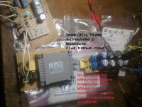
In next pictures, its the 5th TIDU34, on the PCB now.
It sounds BAD with LM317/337...But, when psu is replaced with simple TRAFO-CRC filter, the sound becomes VERY NICE again.
Modified the input filter... removed the capacitor, replaced 3.3nF with 1nF COG. Resulting in more detailed sound and better bass response.
(22uF ceramic vs 10uF electrolytic made no difference for me in tidu34 signal paths).
USE 100R output isolation resistor. And DONT USE WIMA MKT's and whatever random capacitors in decoupling networks
As i have no noise on the output with simple CRC PSU and offset voltage is 0.1-0.4mV, i will stay with CRC. Even with 50mV DC input voltage(without input DC blocking capacitor), i still have 0,1-0,4mV DC on TIDU34 output.
OPA2134 everywhere.
6th Texas will be build on the PCB again using 1st TIDU34 10uf decoupling techniques, LM317/LM337 PSU and 5th texas input filter modifications to get most out of it.
EDIT: 1-2mV was with NE5532 replacing the last two opamps in TIDU34 schematic. BTW, NE5532 is actually more neutral sounding, OPA2134 more agressive.
OPA2134 gets you as close as 0mV
Using OPA2134 and NE5532.
You can get very nice results with LM317 type psu. Its all about the design.
For noobs, i recommend not to use any regulators if you don't know how to make good PSU decoupling networks.
For example, original non-modified design from tidu34 pdf last page sounds good with LM317/LM337. Use 220uf ~250mR ESR@ 100Khz cap on regulators output.
Decouple every opamp psu pin with 10uf 35V miniature Nichicon PW series capacitor(~1.1R ESR@100Khz @ 25C). I used x7R 100nf caps in parallel with 10uF too but not sure if they were needed. It was all done very closely to opamp pins on prototype board. Use ceramics everywhere on feedback networks
, COG type works best.So i modify the first one, add WIMA MKT and TANTALUM as replacement of opamp psu decoupling... FAIL... sound was worse...
I build another one with WIMA 100nf MKT and Electrolytes as paralleled OPA decoupling, again sound is bad.
In next pictures, its the 5th TIDU34, on the PCB now.
It sounds BAD with LM317/337...But, when psu is replaced with simple TRAFO-CRC filter, the sound becomes VERY NICE again.
Modified the input filter... removed the capacitor, replaced 3.3nF with 1nF COG. Resulting in more detailed sound and better bass response.
(22uF ceramic vs 10uF electrolytic made no difference for me in tidu34 signal paths).
USE 100R output isolation resistor. And DONT USE WIMA MKT's and whatever random capacitors in decoupling networks
As i have no noise on the output with simple CRC PSU and offset voltage is 0.1-0.4mV, i will stay with CRC. Even with 50mV DC input voltage(without input DC blocking capacitor), i still have 0,1-0,4mV DC on TIDU34 output.
OPA2134 everywhere.
6th Texas will be build on the PCB again using 1st TIDU34 10uf decoupling techniques, LM317/LM337 PSU and 5th texas input filter modifications to get most out of it.
EDIT: 1-2mV was with NE5532 replacing the last two opamps in TIDU34 schematic. BTW, NE5532 is actually more neutral sounding, OPA2134 more agressive.
OPA2134 gets you as close as 0mV
Attachments
.JPG)
Last edited:
Hi Rensli,
Nice diy work. Can you mark up your final values on tidu schematic (posted by APEX on http://www.diyaudio.com/forums/soli...imate-fidelity-amplifier-590.html#post4564225 Post #5898).
Reg
Prasi
Nice diy work. Can you mark up your final values on tidu schematic (posted by APEX on http://www.diyaudio.com/forums/soli...imate-fidelity-amplifier-590.html#post4564225 Post #5898).
Reg
Prasi
I will make another new thread in the future or just continue the "active volume control" @ diyaudio thread... there is more tests i want to do or it will be "jump into conclusion's" story again
My goal is to make it work with low-cost OPA2134 using regulated PSU again and compare between different builds, PSU via. Relay's Switch.
No more hijacking of sir. apexaudio thread from me.
My goal is to make it work with low-cost OPA2134 using regulated PSU again and compare between different builds, PSU via. Relay's Switch.
No more hijacking of sir. apexaudio thread from me.
Last edited:
I have played with TIDU34 project for about a year now.
Using OPA2134 and NE5532.
You can get very nice results with LM317 type psu. Its all about the design.
For noobs, i recommend not to use any regulators if you don't know how to make good PSU decoupling networks.
For example, original non-modified design from tidu34 pdf last page sounds good with LM317/LM337. Use 220uf ~250mR ESR@ 100Khz cap on regulators output.
Decouple every opamp psu pin with 10uf 35V miniature Nichicon PW series capacitor(~1.1R ESR@100Khz @ 25C). I used x7R 100nf caps in parallel with 10uF too but not sure if they were needed. It was all done very closely to opamp pins on prototype board. Use ceramics everywhere on feedback networks
So i modify the first one, add WIMA MKT and TANTALUM as replacement of opamp psu decoupling... FAIL... sound was worse...
I build another one with WIMA 100nf MKT and Electrolytes as paralleled OPA decoupling, again sound is bad.
In next pictures, its the 5th TIDU34, on the PCB now.
It sounds BAD with LM317/337...But, when psu is replaced with simple TRAFO-CRC filter, the sound becomes VERY NICE again.
Modified the input filter... removed the capacitor, replaced 3.3nF with 1nF COG. Resulting in more detailed sound and better bass response.
(22uF ceramic vs 10uF electrolytic made no difference for me in tidu34 signal paths).
USE 100R output isolation resistor. And DONT USE WIMA MKT's and whatever random capacitors in decoupling networks
As i have no noise on the output with simple CRC PSU and offset voltage is 0.1-0.4mV, i will stay with CRC. Even with 50mV DC input voltage(without input DC blocking capacitor), i still have 0,1-0,4mV DC on TIDU34 output.
OPA2134 everywhere.
6th Texas will be build on the PCB again using 1st TIDU34 10uf decoupling techniques, LM317/LM337 PSU and 5th texas input filter modifications to get most out of it.
EDIT: 1-2mV was with NE5532 replacing the last two opamps in TIDU34 schematic. BTW, NE5532 is actually more neutral sounding, OPA2134 more agressive.
OPA2134 gets you as close as 0mV
May I ask what you are powering with this psu that simple changes in the power supply make it sound horrible? I want to avoid that circuit. Can you describe the A/B setup you are using to test for audible differences?
Thanks, Terry
Last edited:
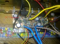
NEW TEXAS by oscillator2 | Photobucket
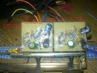
TO avoid hijacking, i published photos of the regulator and the 1st successful Texas that worked very well with this regulator. All info are in photo description, also speaker and amp setup and schematic!
EDIT: Regulators are from texas: LM317AT and LM337AT (they are thicker-wider package type).
I now remember why i did "f***" up the 1st texas. It had so many connection "wires"... so i re-routed some, shared routes, changed decoupling caps and all that was in the name of simplicity... but it turned out i ruined the sound too
Amplifier is 100% oscillation free, with ~25mA Output stage bias, the heatsink is not even warm, i listen to it mostly @ few watts, room temperature ~25C
When i am @ ~40W into 8R stereo, heatsink is just a bit warm, say 40C.
I agree we should not be hijacking this thread with discussion about non Apex equipment.
It is not hijacking with schematic in post #5898 and pcb made by prasi it is part of this thread.
It is not hijacking with schematic in post #5898 and pcb made by prasi it is part of this thread.
Is that your design?
I now remember why i did "f***" up the 1st texas. It had so many connection "wires"... so i re-routed some, shared routes, changed decoupling caps and all that was in the name of simplicity... but it turned out i ruined the sound too
I know that you are using memory for comparison and I'm completely okay with that (but some others, mostly those with bad ears, will look at it suspiciously).
But there are too many things that will affect the sound/result, such that you have to be careful to state your conclusion, because with different implementation, the conclusion will be different.
I think the original circuit uses very fast opamp (may be faster than OP2134). Have you tried to adjust 100pF across feedback resistor? I think it's too big. An RC with 22n could be fine, who knows (I'm not going to discuss its audibility
but reducing the input filter is usually audible for me too as it affects phase at HF).BTW, using tantalum alone might ruin the sound. I have never found any single implementation where tantalum capacitor is okay for sound.
- Home
- Amplifiers
- Solid State
- 100W Ultimate Fidelity Amplifier