Hi, just a few small steps forward ...@olafk soon you will release an improved layout for the A14? I'm interested of this project.....and I'm wondering if this amplifier can run in bridged mode.
Thanks a lot.
Why a complex hifi bridge amplifier with 2 x 50W? You can find a lot of amplifiers with 100 to 200W here.
regards Olaf
Attachments
HI, because my power supply have only +-36V after filtering caps. An exampfe of 100W power amplifier is A23 or A33?Hi, just a few small steps forward ...
Why a complex hifi bridge amplifier with 2 x 50W? You can find a lot of amplifiers with 100 to 200W here.
regards Olaf
Regards.
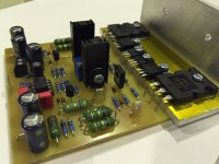
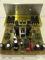
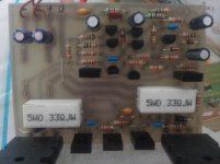
Hi,
here are some pictures of A14. Now ready and works.
Will make some measurements tomorrow.
regards Olaf
Nice work, I suggest OPA604 or OPA134 instead TL071.
Regards
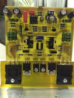
I have made AX-14 , but there is some problem ...
I can`t adjust bias ..
The sound is very quiet and like radio with no signal .
I checked all transistors - they are fine .
All passive elements are on place , with correct values .
drivers are KSE340 , KSE350
It work on +-43V
Any idea ?
I can`t adjust bias ..
The sound is very quiet and like radio with no signal .
I checked all transistors - they are fine .
All passive elements are on place , with correct values .
drivers are KSE340 , KSE350
It work on +-43V
Any idea ?
Attachments
I have made AX-14 , but there is some problem ...
I can`t adjust bias ..
The sound is very quiet and like radio with no signal .
I checked all transistors - they are fine .
All passive elements are on place , with correct values .
drivers are KSE340 , KSE350
It work on +-43V
Any idea ?
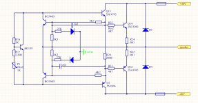
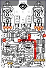
hello sir I do not see the trim pot on the board how do you adjust bias with out it ?

uhmmm ... the driver are KSE340 , KSE350 ?, ok this devices the leads are
E C B and on the PCB is B C E try find ones driver that are B C E
not E C B unless ..... uhmmm ..... did you rated them 180 degree ?
Regards
Juan
Attachments
Last edited:
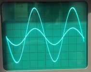
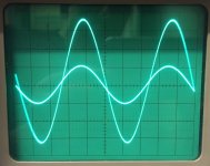
Hi, here are a few photos from the oscilloscope. Voltages are at 0.4Vpp Input and about 14Vpp at the output. Sine looks good.
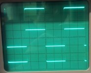
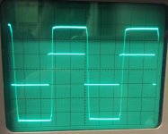
The overshoot at 20kHz square wave seems to be coming from the generator (only a cheap DDS). Unfortunately, there is at 20kHz square wave a high frequency oscillation and the 4R7 from Zobel is very hot and shows a bad smell.
Advice is very welcome.
Regards Olaf
The overshoot at 20kHz square wave seems to be coming from the generator (only a cheap DDS). Unfortunately, there is at 20kHz square wave a high frequency oscillation and the 4R7 from Zobel is very hot and shows a bad smell
.Advice is very welcome.
Regards Olaf
Attachments
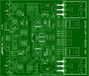
First let's find some errors then I will publish the files.Hi @olafk , that's the new release of the A14? Can you post the pdf files?
Thank you.
regards Olaf
hello sir I do not see the trim pot on the board how do you adjust bias with out it ?
uhmmm ... the driver are KSE340 , KSE350 ?, ok this devices the leads are
E C B and on the PCB is B C E try find ones driver that are B C E
not E C B unless ..... uhmmm ..... did you rated them 180 degree ?
Regards
Juan
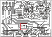
Can't see from the photo but also make sure jumper for output of the 5200 is installed.
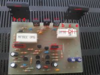
I don't know if this help but look at my custom made PCB maybe you will find a difference or something odd "weird", check for traces that might be jumped with solder or is a trace that is not having good contact are those all original transistors ? and not "e-bay" type hold one I see that you are using 10R resistor for the base of the power transistors ? I'm not sure if that might be the problem. it should work
Attachments
Last edited:
Hi, do you mean that it is normal at 20kHz and high amplitude?Pushing high frequency square waves at high amplitude will make the Zobel very hot, even can burn it out.
With normal music and lower frequency square wave all is cool.
- Home
- Amplifiers
- Solid State
- 100W Ultimate Fidelity Amplifier