You have mirror reverted pcb sides top and botom, you must put components on cooper side of pcb
I see what you mean. I have to print a new board.
Regards,
Paulo.
")
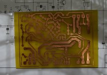
It's correct,Apex,
I made a new pcb. Is this board correct?
Thank you for your help.
Regards,
Paulo.
Regards
Polarity for D4 & D5 on AX14
Dear APEX,
I have build AX14 using your PCB & layout in post #62.
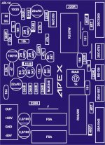
I found one mistake in the blue component layout diagram: the polarity of D4 & D5 are reversed. I used 33ohm as current limiting resisters and they glows red on power up. I removed D4 & D5 and the amplifier works fine.
I am not using C1 (DC-blocking capacitor) and I found that DC offset is more than 100mV.
I made the following changes:
Substituted Q1 & Q2 with BC560C, DC offset is back to 16mV
Q8 with BF469 & Q9 with BF470 because I got them in my parts bin.
The amp sounds great & I will do more critical listening.
Thanks for sharing the circiuit.
Cheers, Stanley
Dear APEX,
I have build AX14 using your PCB & layout in post #62.
I found one mistake in the blue component layout diagram: the polarity of D4 & D5 are reversed. I used 33ohm as current limiting resisters and they glows red on power up. I removed D4 & D5 and the amplifier works fine.
I am not using C1 (DC-blocking capacitor) and I found that DC offset is more than 100mV.
I made the following changes:
Substituted Q1 & Q2 with BC560C, DC offset is back to 16mV
Q8 with BF469 & Q9 with BF470 because I got them in my parts bin.
The amp sounds great & I will do more critical listening.
Thanks for sharing the circiuit.
Cheers, Stanley

input offset current, input offset voltage, output offset voltage.I am not using C1 (DC-blocking capacitor) and I found that DC offset is more than 100mV.
I made the following changes:
Substituted Q1 & Q2 with BC560C, DC offset is back to 16mV
Your change affected all of these. Do you know why?
DC Offset
Andrew,
I should clarify:
2N5401 installed as Q1 & Q2,
Output DC offset voltage = 14mV (with DC-block capacitor)
Output DC offset voltage > 100mV (without DC-block capacitor)
BC560C installed as Q1 & Q2,
Output DC offset voltage = 4mV (without DC-block capacitor, input open)
Output DC offset voltage = 16mV (without DC-block capacitor, input connected to 15K resistor + 10K Pot)
I guessed that the BC560C got higher gain than 2N5401 so BC560C requires less input offset current.
This amp has got good bass, but I found that the treble is a bit harsh for my setup. It is OK for low-volume background music but it is a bit tiring at higher volume. I may reconnect the input DC-block capacitor & comapre.
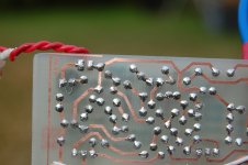
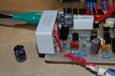
I attached a few pictures here. The last pic shows the input capacitor was bypassed with a link.
- Stanley
input offset current, input offset voltage, output offset voltage.
Your change affected all of these. Do you know why?
Andrew,
I should clarify:
2N5401 installed as Q1 & Q2,
Output DC offset voltage = 14mV (with DC-block capacitor)
Output DC offset voltage > 100mV (without DC-block capacitor)
BC560C installed as Q1 & Q2,
Output DC offset voltage = 4mV (without DC-block capacitor, input open)
Output DC offset voltage = 16mV (without DC-block capacitor, input connected to 15K resistor + 10K Pot)
I guessed that the BC560C got higher gain than 2N5401 so BC560C requires less input offset current.
This amp has got good bass, but I found that the treble is a bit harsh for my setup. It is OK for low-volume background music but it is a bit tiring at higher volume. I may reconnect the input DC-block capacitor & comapre.
I attached a few pictures here. The last pic shows the input capacitor was bypassed with a link.
- Stanley
Attachments
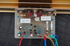
D4 polarity reverted on component layout, you add some extra caps?Dear APEX,
I have build AX14 using your PCB & layout in post #62.
I found one mistake in the blue component layout diagram: the polarity of D4 & D5 are reversed. I used 33ohm as current limiting resisters and they glows red on power up. I removed D4 & D5 and the amplifier works fine.
I am not using C1 (DC-blocking capacitor) and I found that DC offset is more than 100mV.
I made the following changes:
Substituted Q1 & Q2 with BC560C, DC offset is back to 16mV
Q8 with BF469 & Q9 with BF470 because I got them in my parts bin.
The amp sounds great & I will do more critical listening.
Thanks for sharing the circiuit.
Cheers, Stanley
Regards
Capacitors
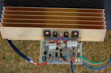
I added two rail bypass capacitors (1.5uF X7R ceramic) closer to the output transisitors.
I found the treble is a bit harsh if I removed the input capacitor (C1).
I put back C1 & that removes the harshness.
I replaced C1 (10uF Bipolar electro) with 10uF film capacitor & the high frequencies is a bit smoother.
I left the BC560C installed at Q1 & Q2 as they gives lower Output DC offset compared with the 2N5401.
Cheers, Stanley
D4 polarity reverted on component layout, you add some extra caps?
Regards
I added two rail bypass capacitors (1.5uF X7R ceramic) closer to the output transisitors.
I found the treble is a bit harsh if I removed the input capacitor (C1).
I put back C1 & that removes the harshness.
I replaced C1 (10uF Bipolar electro) with 10uF film capacitor & the high frequencies is a bit smoother.
I left the BC560C installed at Q1 & Q2 as they gives lower Output DC offset compared with the 2N5401.
Cheers, Stanley
Attachments
What is your bias current value? Is DC offset stable? Where you connect gnd from psu to input gnd? Try to remove 100nF from input gnd to power gnd. Put amp in metal case, and connect gnd to the case.I added two rail bypass capacitors (1.5uF X7R ceramic) closer to the output transisitors.
I found the treble is a bit harsh if I removed the input capacitor (C1).
I put back C1 & that removes the harshness.
I replaced C1 (10uF Bipolar electro) with 10uF film capacitor & the high frequencies is a bit smoother.
I left the BC560C installed at Q1 & Q2 as they gives lower Output DC offset compared with the 2N5401.
Cheers, Stanley
Regards
Last edited:
What is your bias current value? Is DC offset stable? Where you connect gnd from psu to input gnd? Try to remove 100nF from input gnd to power gnd. Put amp in metal case, and connect gnd to the case.
Regards
Bias current is about 120ma and it is stable & I like slightly warm heatsink.
Output DC offset for 2N5401 is about -17mV with C1 installed
Output DC offset for BC560C is about -7mV with C1 installed
DC offset is stable.
I connect the input ground to PSU ground via a separate wire.
The amp has no hum & no hiss; I will try the other suggestions.
Cheers, Stanley
Do you measure hfe of 2N5401 or BC560C, with same hfe DC offset will be low, but stable value is most important, anyway you can adjust offset to zero. If you test amplifier with different speakers or compare with another amp, please share your expiriance.Bias current is about 120ma and it is stable & I like slightly warm heatsink.
Output DC offset for 2N5401 is about -17mV with C1 installed
Output DC offset for BC560C is about -7mV with C1 installed
DC offset is stable.
I connect the input ground to PSU ground via a separate wire.
The amp has no hum & no hiss; I will try the other suggestions.
Cheers, Stanley
Regards
Last edited:
Bridge output use outputs from two amplifiers noninverted (+) and inverted (-) without useing GND, you can use noninverted output (+) and GND and connect from 10k resistor to 1k pot for volume control, but I suggest to use subwoofer X-over from thread post #102 :Hi Apex,
I am planning to build your AX-14 Amp for my car subs. The problem is, the output of the car stereo is bridge. How can I connect it?
http://www.diyaudio.com/forums/solid-state/167363-mic-line-eq-preamps-11.html
Regards
Yes amp will work, please post pictures and share expirience. I want to make this 'UltiAmp' best choice for DIY amp, and you help other diyers to discover all adventage of this circuit.Thanks Apex... just to crarify, can it be powered by +-35V and a load of 4 ohms?
Regards
Last edited:
- Home
- Amplifiers
- Solid State
- 100W Ultimate Fidelity Amplifier