hello sir apex, can i replace with this transistor the bd139, bc639,and bc640? this are the available parts in our place. i am going to build your ax11 for home listening music
bd139- mje340, bd135, bd137
bc639- 2sd667, 2sc2383
bc640- 2sb647, 2sa1013, bc327
thanks,joeyt
bd139- mje340, bd135, bd137
bc639- 2sd667, 2sc2383
bc640- 2sb647, 2sa1013, bc327
thanks,joeyt
hello sir apex,
can i use a 10 amperes bridge rectifier diode for 1 channel? for ax11
thanks,joeyt
Yes, 10A is ok for stereo with +/-35V rail.
hello apex sir i need add 0.1uf and 10 ohm 5watt resister in series at APEX AX-14 speaker terminal or no need
Yes, zobel network must be add
Sir Apex can i use irfp640 in nx-14? and if i can use, how much max voltage supply? Thanks
Use IRF540 with +/-40V maximum rail voltage.
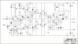
Yes shematic in this point is wrong but pcb is o.k.
By the way this is shematic for AX11.
and what would be the effect if its connected?..i saw those other design emitter of driver transistors are connected in output stage..
Nice Willy very nice. hey my man I'm putting together your version of AX-11 MKII and well if some one can help me out I will really appreciated,today I'm putting together must of the component I have on hand I just need to get me the transistor MPSA-92,BD679A,MJ15003/4,MJE15030/1, and resistors 4R7/1W and the emitter resistors 0.22/5W, so far is going well
Regards
Vargas
ok I am using Willy's TO-3 version PCB but for the use of 2n5551 I think the silkscreen file is wrong. The originally spec'd BC546 goes C(1)B(2)E(3) but all the datasheets for 2n5551 go E(1)B(2)C(3) when looking at the flat side as "front"
Has anyone built the AX-11 TO-3 version with 2n5551 at the front end and can verify this?
Attachments
AX14P
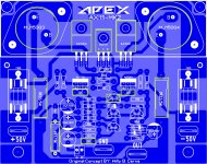
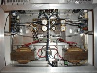
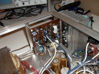
P { margin-bottom: 0.21cm; } Hi Dear mister Mile ! I have changed a little beat my initial plans, because I decided to give a gift to my nephew and I did your AX14P first, for him. I should say something for you, the world needs persons like you to go further, because you teach and share your knowledge. I changed a litlle beat your design about AX14 PCB, and I put the protection there, C7 33pF, C9 C10 22pF, Q1, Q2, Q3 2SA970.
For those wants to do de same amplifire here is, this PCB only needs a correct components on the correct place, nothing more nothing less... No PCB errors, no hummms, no noises, no nothing... the only thing is a very good sound, everything is OK, good and natural healthy bass, very clear and sweet midle and crystalline high. Next project, is AX20 for me.
Thanks Mister Mile
Attachments
-
 APEX AX14 with Protec.jpg519.5 KB · Views: 1,293
 -
Apex AX14P copper side.pdf142.7 KB · Views: 751
-
Apex AX14P Components.pdf179.4 KB · Views: 852
-
 AX14P-6.jpg353 KB · Views: 707
 -
 AX14P-5.jpg366.8 KB · Views: 639
 -
 AX14P-4.jpg412.2 KB · Views: 610
 -
 AX14P-3.jpg415.4 KB · Views: 601
 -
 AX14P-2.jpg347.6 KB · Views: 1,915
 -
 AX14P-1.jpg672.8 KB · Views: 2,269
P { margin-bottom: 0.21cm; } Hi Dear mister Mile ! I have changed a little beat my initial plans, because I decided to give a gift to my nephew and I did your AX14P first, for him. I should say something for you, the world needs persons like you to go further, because you teach and share your knowledge. I changed a litlle beat your design about AX14 PCB, and I put the protection there, C7 33pF, C9 C10 22pF, Q1, Q2, Q3 2SA970.
For those wants to do de same amplifire here is, this PCB only needs a correct components on the correct place, nothing more nothing less... No PCB errors, no hummms, no noises, no nothing... the only thing is a very good sound, everything is OK, good and natural healthy bass, very clear and sweet midle and crystalline high. Next project, is AX20 for me.
Thanks Mister Mile
Nice work,
Regards
Hi Mr. Mile..
can u upload Layout this shematic..
very thank before..
sory, my grammar is bad
can u upload Layout this shematic..
Pre-amp for ultimate fidelity.
very thank before..
sory, my grammar is bad
ok I am using Willy's TO-3 version PCB but for the use of 2n5551 I think the silkscreen file is wrong. The originally spec'd BC546 goes C(1)B(2)E(3) but all the datasheets for 2n5551 go E(1)B(2)C(3) when looking at the flat side as "front"
Has anyone built the AX-11 TO-3 version with 2n5551 at the front end and can verify this?
OK,
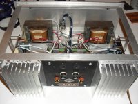
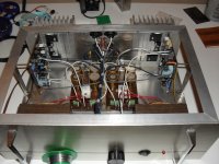
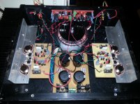
Got my 2n5551's all straightened out and in the correct way.
Both channels just fired up and all is well!!!
V+/- = 34V
dropping 34mV across the 0.22R resistors = 154mA
3k3R across the bias network was obviously way to high
funny though...2K2 wouldnt bias up...I had to play with some parallel resistors across the 3k3 to get it to bias...ended up somewhere around 2K7 for the above values.
I thought I blew a fuse when I turned it on - it is that darn quiet.
Still need to get a couple more pieces of hardware and clean the wiring up a bit but for now its good to go!
Thanks for the circuit and PCB design guys!
Attachments
OK,
Got my 2n5551's all straightened out and in the correct way.
Both channels just fired up and all is well!!!
V+/- = 34V
dropping 34mV across the 0.22R resistors = 154mA
3k3R across the bias network was obviously way to high
funny though...2K2 wouldnt bias up...I had to play with some parallel resistors across the 3k3 to get it to bias...ended up somewhere around 2K7 for the above values.
I thought I blew a fuse when I turned it on - it is that darn quiet.
Still need to get a couple more pieces of hardware and clean the wiring up a bit but for now its good to go!
Thanks for the circuit and PCB design guys!
Nice work, what about sound?
Regards
- Home
- Amplifiers
- Solid State
- 100W Ultimate Fidelity Amplifier