Badboy,
Thank you for your answer.
I use to listen one amplifier I projected more than 10 years ago. I could get the maximum from my old B&W DM604 speaker.
My one is a good amplifier and was based in gain-bandwidth product. I used the Leach Book as reference to project this old amplifier and also used informations from some patents in audio.
I am attaching the simulation of your circuit and my circuit version with corrections and changes.
It was done with LTSpice, so you can download and test my changes. Here in the forum you can find all data and information to learn to use it as I did.
I asked about PCB as the decoupling depends from your layout. My simulation schematics do not comply it. If you change this circuit and make a new PCB I wonder to have a free pair. I am also Eagle user.
Regards
Ronaldo
Do you have the schematic of your amp??? how much power you get from it ???
My amplifier was based in Mark Levinson 27.5 Schematic.
Math was done based in Leach Book as I wrote you.
I found only PCB images in my laptop. I also have pictures in someplace. I did not find schematics. It is lost in somewhere in some old computer.
It is only 70W in 8R. Around 100W in 4R. Uses only 1 output pair.
Did you saw simulations?
It is the subject of this thread. As I wrote you, if you think my changes are helpful and you decide to make a new PCB I can help you also in PCB layout. My 2 cents is a pair of revised boards.
Ronaldo
Attachments
Last edited:
New PCB New Project
Ok thank you.
This SIM is just for reference. It is used only to see amplifier working with no charges. Normally you have better results in SIM . Real amplifier is a different beast.
There are other changes to improve your project.
The changes makes a really good square wave behavior. With changes you can use it to listen music, not only a subwoofer amplifier.
It is an interesting amplifier idea.
Regards
Ronaldo
Last edited:
Ok thank you.
This SIM is just for reference. It is used only to see amplifier working with no charges. Normally you have better results in SIM . Real amplifier is a different beast.
There are other changes to improve your project.
The changes makes a really good square wave behavior. With changes you can use it to listen music, not only a subwoofer amplifier.
It is an interesting amplifier idea.
Regards
Ronaldo
I made all the changes on my current pcb and here's the new output signal at about 400W rms
An externally hosted image should be here but it was not working when we last tested it.
And here's the new schematic :
An externally hosted image should be here but it was not working when we last tested it.
BTW I couldn't lower down C1 to 3.3pf because over current protection on my smps kicks in every time I tried to increase power more than 200W
So I place a 10pf instead
Badboy6120
This 3.3 pF capacitor defines amplifier speed. (it was 220pF). It was the lower value I could use in simulator. Lower than 3.3pF the amplifier becomes unstable and oscillates. More than 3.3pF the slew-rate decreases, but you have a stable amplifier.
Now you are in real world and the things become more real and make REAL sense.
Your scope shows a little noise in the wave. Do you know if it this comes from SMPS?
The best way to test amplifier is using square wave with a dummy load. Could you try it?
Please, let me know your general opinion about the result, so I can continue sending you more information to improve it even more. (I did it in less than half hour - only to see what it does and remove what I thought wrong)
Please, also post a picture of your setup and details about your power supply.
Thank you.
Ronaldo
Last edited:
AbsolutelyYour scope shows a little noise in the wave. Do you know if it this comes from SMPS?
I test this amp with 50 Hz transformer and it gave a clean wave
i even power up the smps with about 1kw when amplifier was working with 50Hz transformer and there was no difference on output signal(the amp was next to the smps)
this proves that this problem is not from magnetic field around smps or even EMI
Right now I'm applying 120Hz sine wave via computer or mp3 playerThe best way to test amplifier is using square wave with a dummy load. Could you try it?
I guess I could use square wave instead
and also all the pictures I sent here was while amplifier connected to 3.8 ohms 260W dummy load I made for my tests
You need a real square wave test signal.
A filtered digital version of a squarewave has too many ripples and a non constant stepped voltage.
I think you should be looking at performance throughout the whole range of output voltages, not just around the near clipping output.
A filtered digital version of a squarewave has too many ripples and a non constant stepped voltage.
I think you should be looking at performance throughout the whole range of output voltages, not just around the near clipping output.
[/QUOTE]Please, let me know your general opinion about the result, so I can continue sending you more information to improve it even more. I did it in less than half hour - only to see what it does and remove what I thought wrong. [/QUOTE]
I'm getting less fuzzy signal in output So I'm absolutely happy about it and appreciate your help
I can't wait to make it even better
The SMPS I'm using is from Ludo design
I made a few changes and increase its power to 1.5Kw continues!!!
I test it about 1 hour with 1500W Heater Elements
Half Bridge
50Khz
+-72V
I'm getting less fuzzy signal in output So I'm absolutely happy about it and appreciate your help
I can't wait to make it even better
I will provide some pictures in less than an hourPlease, also post a picture of your setup and details about your power supply.
The SMPS I'm using is from Ludo design
I made a few changes and increase its power to 1.5Kw continues!!!
I test it about 1 hour with 1500W Heater Elements
Half Bridge
50Khz
+-72V
Last edited:
An externally hosted image should be here but it was not working when we last tested it.
An externally hosted image should be here but it was not working when we last tested it.
An externally hosted image should be here but it was not working when we last tested it.
SMPS still on prototype
I'm waiting to test both my amps with it and then design a pcb for it
SMPS in audio amplifier
Badboy,
I know there are lots of power amplifiers using SMPS. Here in Brazil there is a company called StudioR that uses it. High Quality Professional PA Amplifier.
I also projected SMPS for Telecom application and I needed to make my project comply lots of EMI international rules. It is not easy, in fact it is a very complicated subject and need expensive RF equipment, calibrated antenna and special chamber to make reliable analyze. EMI can be conducted, irradiated or both and there is compatibility issues to be considered between equipments.
There is a fact: No amplifier will fix a defective or bad quality SMPS. So I propose you to test the amplifier with conventional power supply. when it becomes stable and reliable we can change to SMPS.
I believe you have some problems in your modified power supply. It is also other subject.
Yes, this problem with output signal is definitely coming from smps output rails
but I compare sounds coming from 50HZ trafo and my smps at same power output and honestly there is absolutely no difference
the problem with completing this amp project with my 50 Hz trafo is that I can not get more than 200w out of it
I compare sounds coming from 50HZ trafo and my smps at same power output and honestly there is absolutely no difference
Badboy,
Differences in sound quality depends on the acoustic boxes, signal sources, ability to distinguish nuances, personal preferences. It is a subjective judgement. You must be trained and have good quality gear to find differences.
A Scope show you the signal details. No doubt you have problems with your SMPS. You need to solve it to avoid problems.
Attached you have a more correct and complete schematic following your design idea.
I did a new compensation arrangement and you can choose the values you have. Just remember low values can give you oscillation. high values give you slow slew-rate.
I changed R2 and R20 to have better polarization in signal stage.
I add supply decoupling capacitors. It must be well add in your layout to give best effect.
I changed a bit the bias generator to create a more stable current through power MOSFET. The best bias value is 100 mA per device. Here you find best distortion profile.
I also added Vgs protection to power MOSFETS.
I added another capacitors in global feedback. This arrangement was used in some old Krell Amplifiers I had in my laboratory.
L2 in input differential pair reduce distortion. You can assembly without L2.
Have fun
Ronaldo
Attachments
Last edited:
Badboy,
Differences in sound quality depends on the acoustic boxes, signal sources, ability to distinguish nuances, personal preferences. It is a subjective judgement. You must be trained and have good quality gear to find differences.
A Scope show you the signal details. No doubt you have problems with your SMPS. You need to solve it to avoid problems.
Attached you have a more correct and complete schematic following your design idea.
I did a new compensation arrangement and you can choose the values you have. Just remember low values can give you oscillation. high values give you slow slew-rate.
I changed R2 and R20 to have better polarization in signal stage.
I add supply decoupling capacitors. It must be well add in your layout to give best effect.
I changed a bit the bias generator to create a more stable current through power MOSFET. The best bias value is 100 mA per device. Here you find best distortion profile.
I also added Vgs protection to power MOSFETS.
I added another capacitors in global feedback. This arrangement was used in some old Krell Amplifiers I had in my laboratory.
L2 in input differential pair reduce distortion. You can assembly without L2.
Have fun
Ronaldo
Thanks man for all your help and taking time to fix my problem
This schematic definitely needs a new pcb
I will design its pcb and will check with you before making it
")
@ r_merola
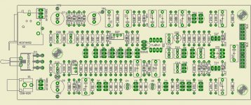
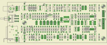
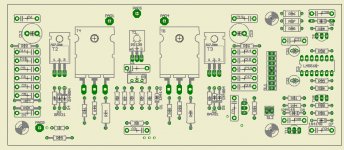
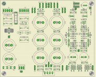
Here's the new pcb :
(please point to me the weak points so I can improve it)
Thanks in advanced
Here's the new pcb :
An externally hosted image should be here but it was not working when we last tested it.
An externally hosted image should be here but it was not working when we last tested it.
(please point to me the weak points so I can improve it)
Thanks in advanced
All the current mirrors operate the transistors at very low Vce.
Swap out the 2n5551/5401 to devices that have excellent near saturation performance.
BC550c/560c or BC337-40/338-40 are cheap and available. Pin out is different.
Move the driver supplies to the rails, but before Vdrop R+D
Change feedback capacitors from 100uF+100uF to 1mF+1mF
Can you buy high voltage, high hFE transistors to replace the input LTP?
I like the feedback arrangement around the VAS/-IN
It is unusual. Could that be causing a stability problem?
The sch has lots of supply rail decoupling. Check you have these in locations that can perform at high frequencies.
Last edited:
- Status
- This old topic is closed. If you want to reopen this topic, contact a moderator using the "Report Post" button.
- Home
- Amplifiers
- Solid State
- 100W Class AB amp