402s? I hope you don't have any isolation boundaries, and 'good luck'.
I just finished radiated emissions/susceptibility on my latest werk, a 120-230VAC input / Relay output module. Dang if the 5mm isolation boundary isn't a real pain in the A**.
Why do we have to make everything so small?
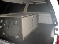
For a change of pace I picked up this behemoth today for free, well three of us almost busted our guts putting it in my truck if that counts as payment.
DC to Light with 2GW output .....
Ok, I lied.
Only 0.015 to 250MHz at up to 200W with 6 tubes in the output. I have no Idea why I got it other than it was to save it from the landfill.
I just finished radiated emissions/susceptibility on my latest werk, a 120-230VAC input / Relay output module. Dang if the 5mm isolation boundary isn't a real pain in the A**.
Why do we have to make everything so small?
For a change of pace I picked up this behemoth today for free, well three of us almost busted our guts putting it in my truck if that counts as payment.
DC to Light with 2GW output .....
Ok, I lied.
Only 0.015 to 250MHz at up to 200W with 6 tubes in the output. I have no Idea why I got it other than it was to save it from the landfill.
Attachments
Last edited:
I need to go find out how my anvils arrived?
(different shipping address from home)
Latest deceased and undesisted horsefloggery:
You might notice the shunts doing *nothing* ???
But thats only at full signal. At lower volume the
idle current would climb insanely high without...
Still this is like 70What?s idle plate dissipation!
Tubelab's drawing crossed plates at 84W...
Don't even want to think bout 980W at peak,
and nothing about peak figure been changed.
Screen bootstrap swings about 80V over the rail.
Min cap value empirically chosen by running sim
20Hz and see what keeps crossing glitch at bay.
G1 drive now totally in A1 with -10V to spare...
G2 currents about 60% what they used to be.
Not sure how G2 got more efficient?
So, is this follower "augmented" at the screens?
Or does pure pentode mode not count?
Attachments
Last edited:
402s? I hope you don't have any isolation boundaries, and 'good luck'.
No, the whole device runs on 7.5 volts. I had to fight off a legion of youngsters who wanted to infiltrate my design with 0201 parts. It turns out that the solder stencil doesn't have enough "dynamic range" for them. I have several big parts like 10 X 10 mm hybrid modules. They require large holes in the stencil which makes it thicker, too thick for 0201's.
These beasts have 15 leads coming out the bottom challenging me to sort them out.
I have it figured out. I can post it when I get home.
They smell like my high school electronics class.
My HS electronics class smelled like ozone and fried parts.
My beef against 201, some clown always puts in the the middle of a long
thin transmission line with no mechanical strength. You merely brush the
201 a bit rough (catch on glove etc..), whole damn trace peels with. You
got a ruined PCB that can't be fixed cause it would screw the impedance...
thin transmission line with no mechanical strength. You merely brush the
201 a bit rough (catch on glove etc..), whole damn trace peels with. You
got a ruined PCB that can't be fixed cause it would screw the impedance...
Same youngsters who put via in pad to wick away all the paste?
We use HDI now. The central core of the board is 6 layers laminated up in the usual way. The outer 2 layers on each side are HDI layers. These are essentially copper plated onto solder mask. The dialectric layer is very thin and the holes are "drilled" with a laser. This allows HDI vias in the pads of even 0201 parts since there is nowhere for solder to go. The drawback, the adhesion is much lower than a conventional board, so it is easy to rip the parts and traces right off the board. The trick is to attach all of the big stuff with core vias that go completely through the board. The dialectric constant for the HDI stuff is different than the conventional layers, so it gets tricky with a RF board, which is what I am doing.
Now back to our live horse..... The transformer.
Primary, for use on US power:
connect the black wire to the black/yellow wire...This is one input connection
connect the black/red wire to the red/green wire ...this is the other input.
Secondaries:
HV is the red wires there is no center tap. Use a FWB or a voltage doubler
Blue is the bias winding about 45 volts
Green is the main 6.3 volt winding green/yellow is the center tap
Yellow is another 6.3 volt winding
Orange is another 6.3 volt winding.
Got my boat anchor order in today and did some tests.
The most important result from a magnetizing current test was that this has a 110 VAC primary(s). Which would explain why the Ebay poster saw so much temperature rise at only a 120 Watt loading. This is a 200 Watt (total) core size for 60 Hz. So connect the Orange 6.8 Vac winding in series with the primary so that a lower secondary voltage occurs. This now gives a 117 VAC primary rating. This will drop the secondary voltage rating from 235 Vac to 220 Vac. But you will be able to run around 900 mA max. on the secondary now (200 Watt, no filaments running). (This is figured using the DC winding resistances of the Primaries and Secondary for 2.5 Watts loss on each side, 5 Watt total DC resistance loss + a few watts loss in the core, you would still want to check the temperature rise to be safe.) Probably was a discontinued xfmr model when someone converted to 117 V primary xfmrs. Sat in some warehouse all these years.
Data:
Blk--Blk/Red primary 1.6 Ohm
Blk/Yel--Red/Grn primary 1.1 Ohm
Red--Red secondary 2.9 Ohm
Blue--Blue bias winding 9.5 Ohm
Grn--Grn filament .1 Ohm approx.
Yel--Yel filament .1 Ohm approx.
Orange--Orange filament .2 Ohm approx.
Blk--Blk/Red to Reds 524 pF (Pri 1 to Sec)
Blk--Blk/Red to Frame 723 pF (Pri 1 to Frame)
Blk--Blk/Red to Blk/Yel--Red/Grn 1025 pF (Pri 1 to Pri 2)
Blk/Yel--Red/Grn to Reds 785 pF (Pri 2 to Sec)
Blk/Yel--Red/Grn to Frame 1352 pF (Pri 2 to Frame)
Both Primaries to Secondary 800 pF
Secondary to Frame 1830 pF
Both Primaries & Orange to secondary 923 pF
Both Primaries & Yellow to secondary 996 pF
Both Primaries & Green to secondary 1018 pF
Both Primaries & Orange & Frame to secondary 1842 pF
Bias to Primaries 376 pF
Bias to Secondary 608 pF
Bias to Frame 501 pF
Grn fil. to Primaries 283 pF
Grn fil. to Secondary 350 pF
Grn fil. to Frame 354 pF
Grn fil. to Primaries & Frame 351 pF
Yel fil. to Primaries 272 pF
Yel fil. to Secondary 330 pF
Yel fil. to Frame 329 pF
Yel fil. to Primaries & Frame 329 pF
Org fil. to Primaries 193 pF
Org fil. to Secondary 214 pF
Org fil. to Primaries & Frame 218 pF
The Orange filament winding has the least capacitance to the secondary, so it's the best one for connecting in series with the primary to get a 117 VAC primary rating.
Last edited:
The Orange filament winding has the least capacitance to the secondary, so it's the best one for connecting in series with the primary to get a 117 VAC primary rating.
I guess you fail to mention the loss of isolation as well? The secondary windings are not constructed or rated for mains isolation from each other.
Could be isolation impaired. Someone with a 1500 V power supply needs to check the breakdown safety between the Orange filament winding and all the other windings. Being it's the lowest capacitance filament winding to all the other windings, the Orange would be the most likely to have decent isolation, but this needs checking. I've got an 800 VAC xfmr here, so I will check for that level at least, but normal Hi-Pot safety tests are more like 2500 V. The measured AC current between windings should only be what the interwinding capacitance would draw. The orange winding seems to be 220 pf to most windings, only 150 pf to yellow or green, about 190 pF to individual primaries.
The magnetizing current was measured at 60 Hz. On 50 Hz this would be a 92 VAC primary.
The magnetizing current was measured at 60 Hz. On 50 Hz this would be a 92 VAC primary.
Last edited:
Well, I measured the leakage currents using my 800 VAC (Hammond 378CX) xfmr using a 140 V variac on the primary to get 968 VAC secondary, which would be 1367 Vpeak.
Results:
Measured AC current in microamps, then measured capacitance in pF
Orange Fil. to Frame: 109.1 uA (215pF)
Orange fil. to Blu bias: 106.6 uA (220 pF)
Orange fil. to Grn fil.: 72.9 uA (148 pF)
Orange fil. to Yel fil.: 74.6 uA (149 pF)
Orange fil. to Red secondary: 107.8 uA (215 pF)
A legitimate Hi-Pot test probably requires some length of time as well. Maybe some temperature ranges too. And certainly more than 968 VAC. The 2500 VAC spec I usually hear is likely for protection in thunderstorms when the mains would get stressed by lightning strikes. You could also put some HV MOVs on the secondary windings (and filament windings) to Earth ground for safety. These would likely increase capacitance to ground to unreasonable levels though for floating windngs such as Circlotron B+ or cathode follower filaments. Without knowing the xfmr design specifics, it would be difficult to tell if all these xfmrs are consistent in their isolation specs without testing a bunch of them too. Would be nice to have a destructive test result too, where the Orange winding voltage (to all other windings and frame connected together) is increased to destructive arc-over. Would give some idea of margin.
Last edited:
The magnetizing current was measured at 60 Hz. On 50 Hz this would be a 92 VAC primary.
Oops... Sorry, it was my completely stupid mistake.

Transient suppressors should be at the primary not secondary. Placing them in the secondary to ground would compromise the isolation and possibly safety.
Hi-Pot is normally a 60 second test (after ramp up if DC) with leakage defined on the order of 1-4mA depending on the test.
At least this is to IEC 61131-2 for industrial controls. This mainly is concerned with operation on primary line voltage up to 600VAC.
I think treating the secondary as if it were the primary and using Table 60 for test voltages would be reasonable. This gives :
300 < Ue <= 600 - 4000V Impulse or 2200VAC 1 minute or 3100VDC 1 minute
600 < Ue <= 1000 - 6000V Impulse, or 3250VAC 1 minute or 4600VDC 1 minute
So for a secondary between 300 and 600VAC one would want to test at 2200VAC for one minute with less than 2mA leakage. Generally once leakage establishes itself above 1mA, it ramps up rapidly above the 2mA limit.
I'll try to remember to ask our safety guy tomorrow. He may be able to point me to a more appropriate spec.
Last edited:
- Status
- This old topic is closed. If you want to reopen this topic, contact a moderator using the "Report Post" button.
- Home
- Amplifiers
- Tubes / Valves
- 10 pounds of power for $15