To each their own.
I'm still loving my old 1980s era Hitachi 2SK133 and 2SJ48 lateral MOSFETs for this. In complimentary class-A, my amp starts cold at 1.65A of idle and drops to a very stable 1.3A when the sink gets warm. Not at all this circuit that I posted, but I love this behavior of lateral mos. The SemiSouth part appear to have the same self-regulating behavior.
I'm still loving my old 1980s era Hitachi 2SK133 and 2SJ48 lateral MOSFETs for this. In complimentary class-A, my amp starts cold at 1.65A of idle and drops to a very stable 1.3A when the sink gets warm. Not at all this circuit that I posted, but I love this behavior of lateral mos. The SemiSouth part appear to have the same self-regulating behavior.
Last edited:
Chance? I don't see it. When bias voltage remains stable as with say a Vbe multiplier not thermally connected to the heatsink, idle current drops as the output devices rise in temperature ensuring a level of stability. Not with your IGBTs, though.. it goes the other way.
It may not run away, but you only get clean AB crossings at one temp.
Unless you do something to tempco your VBE* to match. But then you
back to the hairy edge of runaway again...
Why I say quadrature methods are better. Sample the currents, shape
the desired currents, don't let temperature have a say in the matter.
Do tell your design philosophy to hold the crossing current in spite of tempco?
easy..
1) cold? I don't care that it draws more idle as it'll get warmer because of it
2) hot? Please pull back
This is for a bass amp, not a critical system. Say the amp is hot cause I'm pushing it hard.. I don't care that measurable distortion has increased a few tenths of a percent. damping factor, ring, phase shifted negative impedance loads, for example, are what's important to me.

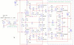
These floated bridge output stages are funny things. Circlotron is new to me. Idle current's going round in circles: supply->device->supply->device, repeat. I can sample it when I add the currents of R21 and R22 together. The signal will cancel (given of course perfect identical gain of each half, which is doubtful such perfection will exist in the real world).
The larger R21&22, the better if looks for idle stability with regards to this stand-in MOS device which is not blessed with neg tempco.
The larger R21&22, the better if looks for idle stability with regards to this stand-in MOS device which is not blessed with neg tempco.
Attachments
Last edited:
Everything looks fine up to C2 + C3. What happpens after is still wishful thinking...
Simulate with SIC Schottky diode shunted across gate to source of your stand-in.
I'll let you cheat and use any stack of diodes that match stand-in VGS threshold.
Watch neg bias voltage buildup on your coupling caps caused by diode pumping.
I am leaving now for more productive topics. Let someone else chime in...

- Status
- This old topic is closed. If you want to reopen this topic, contact a moderator using the "Report Post" button.
- Home
- Amplifiers
- Solid State
- 1.4kW; is this crazy?