You need to measure the inductance in Henries. You need around 150H or preferably more. For the 156C users have put 2 in series back to back and out of phase with each other for a humbucking effect. That can sound better. You need to be aware of hum with the 156C - it's not shielded in any way. If you like the results you might want to upgrade to a Lundahl LL1668 at say 10mA. The LL1668 is reported to sound better than the LL1667 which has more resistance in the coils.Correction
Just measured my chokes on hand.
2.3k ohms.
Too much resistance in that one. If the 01A pulls 8 mA the drop across the choke is 8 x 23 volts.Thanks Andy.
I found my notes from the old amp these came from.
200 Henry and 23k ohms. They should work
What is your B+ voltage to the anode choke?
Check that DC resistance again, preferably with an all analogue meter. The 156C is only 3.7K.
Some modern meters use an AC test signal, the resultant answer is sometimes questionable.
Oops typo not enough coffeeToo much resistance in that one. If the 01A pulls 8 mA the drop across the choke is 8 x 23 volts.
Check that DC resistance again, preferably with an all analogue meter. The 156C is only 3.7K.
Some modern meters use an AC test signal, the resultant answer is sometimes questionable.
2.3 k
Thanks for the formula
1) Are you sure, that it's correct?7.4 v on + heater pin, 4.09v on - heater pin.
7.4-4.09= 3.31V
#01a is requires 5V, 0.25A.
Maybe your raw heater supply hasn't enough voltage for filament biasing.
For example:
5V on filament bias resistor + 5V filament + 5-6V headroom for R.C. regulator: 15-16V DC on R.C. input.
2.)
The Ale's gyrator test points are current measuring resistor (R5)end points.
https://i0.wp.com/www.bartola.co.uk/valves/wp-content/uploads/2019/02/Gyrator-PCB-Rev08-1.jpg
The correct measuring method: measuring voltage BETWEEN test point, then dividing it by 10. This is the current of gyrator.
For example:
100mV/10R= 10mA
BTW it's too much for #01a.
The estimated value is 2 ... 3mA.
I'm a retard...1) Are you sure, that it's correct?
7.4-4.09= 3.31V
#01a is requires 5V, 0.25A.
Maybe your raw heater supply hasn't enough voltage for filament biasing.
For example:
5V on filament bias resistor + 5V filament + 5-6V headroom for R.C. regulator: 15-16V DC on R.C. input.
2.)
The Ale's gyrator test points are current measuring resistor (R5)end points.
https://i0.wp.com/www.bartola.co.uk/valves/wp-content/uploads/2019/02/Gyrator-PCB-Rev08-1.jpg
The correct measuring method: measuring voltage BETWEEN test point, then dividing it by 10. This is the current of gyrator.
For example:
100mV/10R= 10mA
BTW it's too much for #01a.
The estimated value is 2 ... 3mA.
I was looking at the gen 2 schematic and think the 4 was 4 volts not pin 4 of the heater.😒
I adjusted to 5 volts on the heater.
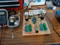
I think my dvm is not measuring milamps . It glowing in the tubes and playing music right now in a test set up and sounds pretty good.
Thank you !

I am back in the corner with the dunce cap on.
I had one of the filaments grounded incorrectly.
I now have both channels voltages correct.
I finally snapped to it after seeing my DMV had a negative on on and positive on the other.
Euro21 thanks for your input.
I have learned much from on many threads here on diyaudio , not just this thread.
I had one of the filaments grounded incorrectly.
I now have both channels voltages correct.
I finally snapped to it after seeing my DMV had a negative on on and positive on the other.
Euro21 thanks for your input.
I have learned much from on many threads here on diyaudio , not just this thread.
Last edited:
Hi,
I have recently purchased 0.22uf Dueland Cast Cu Sn capacitors 600V to be used as the output caps in my 01A that has the SF and I am using an AVC after the preamp.
The Duelund literature says "The outer lead out, closest to the edge of the capacitor, is connected to the outer foil and as such should be connected to the lowest impedance path to ground."
In my preamp one end of the capacitor is connected to the output RCA signal out and the other to the output of the Source Follower.. Where should the outer and inner leads of the Duelund be connected? Confused.
Thank you. nash
Thanks Frentec. I figured it out after realizing that the input impedance of the AVC or even if the 01A is directly connected to a power amp would be several multiplies of the SF. Not much difference tonally with the Duelund connected either way but noticed that instrument placement was a bit better with the outer foil side towards the SF so have left it that way.
After having done this I went ahead and figured out which is the outer foil side on a FT3. To my surprise the FT3 sounds decidedly better with the outer foil side to the SF as opposed to the other way around.
nash
After having done this I went ahead and figured out which is the outer foil side on a FT3. To my surprise the FT3 sounds decidedly better with the outer foil side to the SF as opposed to the other way around.
nash
How much better is the duelund, I’m using Miflex Cu, but upped to 0.47uf for better bassThanks Frentec. I figured it out after realizing that the input impedance of the AVC or even if the 01A is directly connected to a power amp would be several multiplies of the SF. Not much difference tonally with the Duelund connected either way but noticed that instrument placement was a bit better with the outer foil side towards the SF so have left it that way.
After having done this I went ahead and figured out which is the outer foil side on a FT3. To my surprise the FT3 sounds decidedly better with the outer foil side to the SF as opposed to the other way around.
nash
At first I felt that the FT3 was a distant second to the Duelund but after determining the outer foil side of the FT3 and connecting it to the SF(was reversed previously) I rank it a close second.
The timbre of most instruments sound more appealing with the Duelund, especially strings. For the first time I can distinguish the double bass within an orchestra. The Duelund seems to go higher at the high end and lower at the low. Slight less muddiness in the lows; in a piano trio one can more clearly make out the cello from the piano when low notes are played together.
The Duelunds are 25% off at pcx presently.
nash
- Home
- Amplifiers
- Tubes / Valves
- 01A question

