Hey John,
Have you tried a 112A instead?
Personally I've tried and failed to like the 112A. I just find more life and fizz in the 01A, and this matters to me - don't like "flat".
I remember that conversation back in 2012 Andy, have you tried the 112a with gyrator load?
I revisited the 112a not long ago cx-112a DHT preamp – Bartola Valves and it was an interesting experience.
I think it sounds really good. I wish there would be a thoriated tungsten version of the 112a! It’s close to the 01a, but not as good.
Still, though. Is a great valve for a preamp.
Cheers
Ale
I revisited the 112a not long ago cx-112a DHT preamp – Bartola Valves and it was an interesting experience.
I think it sounds really good. I wish there would be a thoriated tungsten version of the 112a! It’s close to the 01a, but not as good.
Still, though. Is a great valve for a preamp.
Cheers
Ale
I'm building an 01a and getting some parts in this week. Putting together Ales boards this weekend but going to evaluate different options with my system. I don't really need the gain of the 01a but want a low impedance output. Ales boards give maximum gain but wondering if a step down 5.6:1 might be better for my amp.
The 112a looks more attractive because of the low Rp but I don't want another 26....
The 112a looks more attractive because of the low Rp but I don't want another 26....
The lower output impedance isn’t provided by a lower Rp in a hybrid mu-follower circuit (e.g. gyrator load). The output impedance is given by 1/gm. As the 112a will run a higher anode current, then the gm of the lower FET device of the gyrator board (either BF862 or BSH111BK for example) will have a higher transconductance. the bigger value in my view is the improvement of the slew rate of the stage. The CX112a will be able to drive more effectively higher capacitive loads (e.g. cables or input transformers of the power amp) which means a crisper HF response.
I didn't know that but have noticed this in my LTSpice modeling...
Would I be better off using another Mosfet in place of the DN2540 to increase transconductance?
The top FET (depletion) takes all the heavy load (HT) and provides enough headroom (VDS) to the bottom device. With a simple design like this, the top device is self biased with the bottom device so you need an IXTP08N100D to provide sufficient VDS to the lower FET so it can operate in optimal conditions (i.e. reduced parasitic capacitances). This will result in better frequency response (and sound in my experience).
With a lower DN2540, you will get a slightly better improve in output impedance, however the frequency response is not as good (as well as the sound) as the LSk170, BF862, etc. An enhancement BSH111BK or BSN20BK will perform better here even at a lower current as their transconductance is higher than the DN2540 at given operating current (e.g. 3mA)
cheers
Ale
Honestly can't remember. I asked Rod Coleman to send me the regulators for this. Just check with him.Ale,
Did you use 1k for R20 and 4ohm for R1 on the Coleman regulator in filament bias on the 01A?
Thanks
Ale
I'm just setting up a 01A pre with a pair of Rod's V2 regs I've had for a while. Can't answer for V7 which i haven't built yet, but really ought to soon. But on the V2 it depends on how starved the filament is. For 200mA and 3.3v i'm using a 5.1R resistor in R1. The more you go up towards the usual 250mA and 5v the lower the resistor becomes. So your choice how much you want to starve the filaments, and then adjust the resistor value to taste.
Hi Andy, Yes, the V7 is programmed for Current in the same way as all versions, including the old V2.
If the nominal filament current is If (Ampère), then calculate R1:
R1 (Ω) = 1/ If (A).
for 250mA 01As, choose R1=3.9Ω. If you want to starve to 200mA, then 4.7 or 5.1Ω will both be in the optimal range.
The trimmer pot allows plenty of adjustment - so you can try different levels of starvation before changing R1. You can try 200mA, even with the standard R1 of 3.9Ω. The optimised level of R1 is only required to give the best dc stability, for long-term running.
I'm setting up a 2P29L to compare with my 01A preamp. I thought I'd economise with a 12v+12v filament transformer with no choke, but it's no dice really. I usually build choke input filament supplies since all my circuits are filament bias, and no choke = detectably sharper sound. I think I may just get away with cap input into a 158T choke, which is 40 ohms, for the 2P29L. It would mean an operating point something like 125v a-k, -5v bias, 15mA. I'd be expecting 13.5v filament supply into Rod's Reg. I'll have to set it up and see if it works.
Well, it doesn't work with CLC, at least not with the 158T which is 40 ohms. I get 12.6v going into the reg. I really should go back to 24+24v and choke input, which I usually do. Obviously doesn't pay to cut corners.
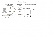
Since there's no 2P29L preamp thread I'll just post the circuit here, for the curious.
Well, it doesn't work with CLC, at least not with the 158T which is 40 ohms. I get 12.6v going into the reg. I really should go back to 24+24v and choke input, which I usually do. Obviously doesn't pay to cut corners.
Since there's no 2P29L preamp thread I'll just post the circuit here, for the curious.
Attachments
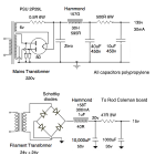
I'd be expecting 13.5v filament supply into Rod's Reg.
If you use 47R 3W (post #253), with 24V AC the raw supply output is only 10V.
With 33R the output voltage is about 11.5V, the R.C. regulator working at the border (120mA).
IMHO this "large" resistor is unnecessary for filtrating, with 4R7 the raw output hum is only 4.5mVpp.
If you want to compromise, with 16R resistor the raw supply is 13.5V (4mVpp).
Attachments
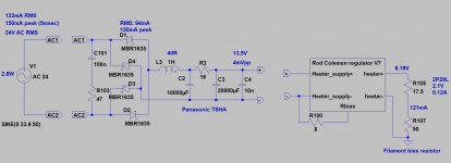
Thanks for the schematic! I've ended up with the supply shown, finished the preamp and listening to it. It's very detailed, as far as I can tell a shade more than my 01A preamp which is the same kind of build. The 01A has a more silky tone quality - the 2P29L is a trifle sharper in the treble. They're both good, really, in different ways.
Attachments
Good job Andy. It was a nice discovery for me the 2P29L. In particular the lack of microphonic noise. Unfortunately I sacrificed the Mule build and morphed it into the new 4P1L. I have gone back to the UV201a with source follower output and this has been my preamp for the last 3-4 weeks. I love the 01a but I have to say that the sound is different from the 2P29L and I like both. In fact the treble of the 01a with the source follower is improved, and very clear. I will build a final version of the 2P29L. At this time I have 4 preamps running which I alternate. The 01a, UV201a version, the 4P1L and the VT-25. I think the four are my top ones and will include the 2P29L as well in that list.
At this time I have 4 preamps running which I alternate. The 01a, UV201a version, the 4P1L and the VT-25. I think the four are my top ones and will include the 2P29L as well in that list.
I have a couple of 01A preamps, the 2P29L now, and a choke loaded 4P1L. I don't have a 10Y although I have plenty of tubes. I want to try out the 26 again with the gyrator - at 7mA it might just drive my PSE 4P1L output stage. What do you think?
These are the contenders, I agree, having heard all of them in various builds. I hope to try your follower PCB soon with the 01A.
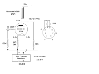
Ale's Gyrator-Filament bias Rod Coleman
I bread boarded the gyrator with the 01A today. I'm new to filament bias so not sure whats going on and starved like Ale does. I have 4volt at top of 20ohm filament resistor and about 7.7 volts at the other end. 4 volt at 20 ohm is 200ma, I assume this is what the Rod Coleman is consuming in current.....50w resistor gets warm Now, when I get to Ale's gyrator and use the test point, I read .117 volts across 10ohms, .117/10ohms is 11.7ma. This tube should be running at about 3ma, any idea whats driving up the current? I have plenty of gain, scope looks good, DN2540 gets warm at that current.

I bread boarded the gyrator with the 01A today. I'm new to filament bias so not sure whats going on and starved like Ale does. I have 4volt at top of 20ohm filament resistor and about 7.7 volts at the other end. 4 volt at 20 ohm is 200ma, I assume this is what the Rod Coleman is consuming in current.....50w resistor gets warm Now, when I get to Ale's gyrator and use the test point, I read .117 volts across 10ohms, .117/10ohms is 11.7ma. This tube should be running at about 3ma, any idea whats driving up the current? I have plenty of gain, scope looks good, DN2540 gets warm at that current.
Last edited:
I have a couple of 01A preamps, the 2P29L now, and a choke loaded 4P1L. I don't have a 10Y although I have plenty of tubes. I want to try out the 26 again with the gyrator - at 7mA it might just drive my PSE 4P1L output stage. What do you think?
These are the contenders, I agree, having heard all of them in various builds. I hope to try your follower PCB soon with the 01A.
Yes, the 26 with the gyrator is superb. I did a quick test and was very happy with it. I will go back to it at some point I will test first the 4P1L in screen mode with some positive voltage on the anode to increase gain. It’d be interesting to see if we can get same good sound with a tad more gain in that configuration.
There are some other valves on the list to try, unfortunately not enough time though.
I’m focusing on a headphone amp as will be getting into flat renovation work and will have to pack all the system up. It will be about 6 months of work so need to survive with a minimum system. We will move out from our place during the work
Would be great if you wonder over before and listen to the latest preamps before I dismantle everything.....
Cheers Ale
Would be great if you wonder over before and listen to the latest preamps before I dismantle everything..... Cheers Ale
Absolutely - I'd love to. I'm pretty free from Tuesday onwards this coming week. Just email me with a date. I'll bring my 2P29L preamp.
The anode voltage is 116v, I assumed that would match the current in your schematic. It sims this way as well.What is the anode voltage? Can you dial the voltage and set the current to 3mA? What would be the anode voltage then?
If I dial it down to 3ma, anode voltage is about 65volts. 3ma simmed at about 95 volts but my tube model could be flawed...
Edit: I bypassed filament bias and used a 2.2K resistor, current at gyrator test point dropped to 2.4ma, I must be doing something wrong with filament bias? Or your diagram is off a little?

Last edited:
- Home
- Amplifiers
- Tubes / Valves
- 01A question