------------------------------------Netlist said:In short: Looking at the upper part of MPL251 which is the drawing of a resistor, you should make a bridge across that 'resistor'.
/Hugo")
Hi Hugo,
Dig it.
I will try that later (or most likely tomorrow), and I'll let you know how I made out.
Thank you *VERY* much!
smiles,
Gregg
----------------------------Netlist said:In short: Looking at the upper part of MPL251 which is the drawing of a resistor, you should make a bridge across that 'resistor'.
/Hugo
Hi Hugo (and GP49),
I couldn't resist the temptation to try it, so I took my stereo cabinet apart, pulled out the Sansui, reattached the wires I had previously removed (and never bothered to put back).
I put a temporary jumper across the two points you showed me in that photo...
...AND...
...
...
...
...
...
...
...
...
...
...
...
...
...(Keep scrolling)...
...
...
...
...
...
...
...
...
...
...
...
...
... ***IT WORKS!!!***
THANK YOU!!!
THANK YOU!!!
THANK YOU!!!
THANK YOU!!!
THANK YOU!!!
THANK YOU TO EVERYONE AT THE FORUM!!!
Very Sincerely Yours,
Gregg
Thanks guys, but most honor goes to our brand new member GP49 for his enlightening tip and to Chris for his endless patience.
Gregg, I'm very happy you fixed that old receiver. Now, it would be even nicer if you could understand what you have done.
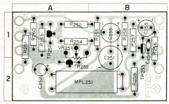
Looking at the schematic, the signal from the tuner comes in at 2X. It goes through the capacitor C253 which is there to block DC voltage. Then it is presented at the Base of transistor 253 and comes out at the Collector. Now you understand that a transistor with three pins has a Base, Collector and Emitter. The emitter is the node with the arrow. The Collector is connected to the 'resistor' of the MPL251 and leaves the circuit via another capacitor C255 (again to block DC) at point 2Y. The 'resistor' works as a gate for the signal the moment the lamp (which is the winded spiral down at MPL251) lights up. In other words the lamp commands the 'resistor' to pass the signal. Transistor 251 and 252 command and regulate the lamp. But that's another story...
/Hugo
Gregg, I'm very happy you fixed that old receiver. Now, it would be even nicer if you could understand what you have done.
Looking at the schematic, the signal from the tuner comes in at 2X. It goes through the capacitor C253 which is there to block DC voltage. Then it is presented at the Base of transistor 253 and comes out at the Collector. Now you understand that a transistor with three pins has a Base, Collector and Emitter. The emitter is the node with the arrow. The Collector is connected to the 'resistor' of the MPL251 and leaves the circuit via another capacitor C255 (again to block DC) at point 2Y. The 'resistor' works as a gate for the signal the moment the lamp (which is the winded spiral down at MPL251) lights up. In other words the lamp commands the 'resistor' to pass the signal. Transistor 251 and 252 command and regulate the lamp. But that's another story...
/Hugo
Hi Hugo,
Many thanks to GP49.
I was thinking. Gregg, try to remove the opto unit and carefully open it up on the lamp side. I have repaired smilar units in the past. Just measure the applied voltage and get a similar lamp. This should be the voltage at 2Z less the drop through the 270 R resistor (less about 0.2V for the transistor). So you could figure this out by measuring that voltage at 2Z. Look at the current draws for lamps less than the measured voltage. eg. 40mA lamp would drop 10.8V across the 270R resistor. You may be able to use an LED by changing the 270 R resistor so it limits the current to 10 ~ 15 mA depending on the LED and the CDS cell in the MPL251. This would give you your soft muting back.
Project for another time?
-Chris
----------------------------Netlist said:...Looking at the schematic, the signal from the tuner comes in at 2X. It goes through the capacitor C253 which is there to block DC voltage. Then it is presented at the Base of transistor 253 and comes out at the Collector. Now you understand that a transistor with three pins has a Base, Collector and Emitter. The emitter is the node with the arrow. The Collector is connected to the 'resistor' of the MPL251 and leaves the circuit via another capacitor C255 (again to block DC) at point 2Y. The 'resistor' works as a gate for the signal the moment the lamp (which is the winded spiral down at MPL251) lights up. In other words the lamp commands the 'resistor' to pass the signal. Transistor 251 and 252 command and regulate the lamp. But that's another story...
/Hugo
Hi Hugo,
When it is explained to me like that I understand it. My problem with schematics is a simple matter of confusing the symbols. For example, I understood the circuit when you showed me the "Block Diagram" with the jumper highlighted. I didn't merely just put a jumper there and not bother to understand it. I looked at the block diagram to try to understand what was going on.
By the way, I didn't put a jumper at that spot. I was a bit more clean about it. (Others might say "sneaky"). The way the board is attached to the unit leaves one of two ways of doing it. (Note: The board is ground-soldered to the chassis and there are a ton of wires bound together at the same spot, making it difficult to work on the under side of the circuit board). I could have done it the easy way, which would have been to solder a wire on top of the circuit board at those two points you highlighted.
However, considering this was a "permanent" fix (due to a lack of replacement part availability), and considering I really don't like doing "sloppy work" like running jumper wires across the top of circuit boards... If you look at the photo you attached, and look at "+" side of C255, and the "R" side of R258, on the back of the board itself there is less than 1/8th of an inch distance between those two points. I cut a 1/8" piece of wire (from a spare ceramic capacitor) and laid it across those to points. Then I tack-soldered each end and flowed a thin layer of solder across those two points.
By looking at it, you would never know I worked on it. That is what I meant by "sneaky." The only way to tell what I did is to know (from looking at the schematic) what you are looking at. There are some techs who would be very annoyed at a job like that. If the part was available, I would have done it with an *obvious* jumper wire. However, since there is zero chance of that circuit ever being repaired "properly," and because the repair itself is not likely to be the cause of any further circuit failure... For that reason I feel okay about doing the repair in such a manner that it cannot be seen.
In my mind it is merely a "clean" repair. However, I realize that there are some who get very frustrated over such "sneaky" stealth repairs.
Again, my most sincere thanks to everyone who helped me with this. I made a PayPal donation to the site as my way of showing my appreciation.
BIG smiles,
Gregg
-------------------------anatech said:...try to remove the opto unit and carefully open it up on the lamp side. I have repaired smilar units in the past...
...Project for another time?
-Chris
Hi Chris,
I have two concerns regarding that project. First, remember what happened when I removed the two pins from the F-1006A MPX circuit board? (The foil pulled off the back of the circuit board). The foil is extraordinarily fragile for some reason. (Age?). When I consider that the only way to reach the MPL251 component would require that I unsolder the circuit board ground to the chassis, I am worried about the amount of heat required to do it. There is a huge mound of solder at that ground.
My second concern would be getting the math correct for the replacement light. If I don't get it just right I could wind up with a "flicker" problem that will leave me with the mute rapidly kicking in and out.
It's a good idea, but for now I'm kinda happy that it's working fine, with the only casualty being the analog gauge of my Multimeter. I am convinced that is just a coincidence because I wasn't doing anything that should have fried it.
In the mean time I do have another project which I am about to begin. I bought a pair of factory built Heathkit AA-13 Mono Amps. I bought all new Electrolytic Capacitors for them, most of which arrived yesterday.
I have a question about that which I will post in a separate thread.
smiles,
Gregg
GLAD I could help!
I'd registered to the diyAudio forum in October, researching another topic, and just sort of stubbed my toe on the Sansui 5000 Help thread. Somehow I just thought, "I'll bet I know what the problem is," and couldn't resist mentioning what little I remember about it. That was an extremely common failure.
You're such a friendly group, it's sort of a shame to solve the problem that had you all teaming up on it. But I can just visualize Gregg jumping up and down and laughing/crying with joy when he heard FM through his Sansui!
May we meet again here...someday.
-Gene
Hi Gene,
Your experience is always welcome here. Many thanks for the hint! May you benefit from someone here in the future!
There are always differing opinions and personalities. Therefore, try not to let anyone get under your skin. Generally an awfully good place to be.
-Chris
Your experience is always welcome here. Many thanks for the hint! May you benefit from someone here in the future!
There are always differing opinions and personalities. Therefore, try not to let anyone get under your skin. Generally an awfully good place to be.
-Chris
--------------------GP49 said:...But I can just visualize Gregg jumping up and down and laughing/crying with joy when he heard FM through his Sansui!
May we meet again here...someday.
-Gene
Hi Gene,
Thank you *VERY MUCH* for deciding to "ruin the fun" of trying to figure it out.
Yes, I did *literally* jump up and down when the fix worked! I was beginning to feel defeated, and that fix really made my entire month.
And yes, "may we meet again here...someday."
smiles,
Gregg
labjr said:I fixed one of these today. Same problem no FM.
Glad I found the fix here. The receiver has sentimental value. The guy bought it during Viet Nam.
Thanks
I'm very happy that everything I went through to resolve this problem, has resulted in helping someone else. That was the whole point of documenting the entire affair.
smiles,
Gregg
I have the same issue (I believe) as gwyz with my Sansui 5000a. No FM. Yes the Stereo light was out but I replaced it with a 6.3 150ma lamp. That did nothing. Then I thought I could do the bridge trick on the 1120 board but I can't even find the 1120 board. None of the boards are marked with this. It's not the FM tuner board is it. Anyway, I have the portion of the schematic that was attached. If I could find the board, I believe I could do it (though I'm a total hack) and can't even read a schematic. Help!
Tried to email Netlist but my account is being monitored because I'm new - says I need to make a few posts before emailing directly. If any of you could cut and paste this into an email to him, I'd be 'abliged to ya'. Thanks.
Tried to email Netlist but my account is being monitored because I'm new - says I need to make a few posts before emailing directly. If any of you could cut and paste this into an email to him, I'd be 'abliged to ya'. Thanks.
If I recall correctly, it's a small board underneath with a small number (maybe 20) of parts on it. I just soldered a little jumper in place where red line is and it fixed the FM.
Here's a picture of the board.
http://www.diyaudio.com/forums/attachment.php?postid=760450&stamp=1131295854&
Here's a picture of the board.
http://www.diyaudio.com/forums/attachment.php?postid=760450&stamp=1131295854&
Wow! Awesome thread!! I do not own one of these recievers but just couldnt help but read this thread anyway. This site is amazing!! I've been to lots of sites with lots of brilliant people on different threads and have even seen posts from some of those same people here on this site. The problem is that, on other sites noboby has the patience to really help someone out and alot of times you are made to feel inferior or ignorant and after just a few posts, I always see people looking for help getting their outstreched hand slapped away with the same old response "Take it to a professional". Well, I was pleasantly suprized to see that was not the case on this thread and seems to be on this whole site. Kudos to you all!!!
- Status
- This old topic is closed. If you want to reopen this topic, contact a moderator using the "Report Post" button.
- Home
- Amplifiers
- Solid State
- Need help with Sansui 5000