Actually i use the G2 instead of G1 for modulation so it is a triode with a shield (G3). G1 is shorted to C so it is not floating or can run away.@Lampie519 I have dismissed the PL519 family earlier because of low Pa, but yes two in // could just about cut it in my app (10mA at 3600V quiescent).
But the need for a G2 supply is a complicating factor in my design (details later) so I would prefer a triode or beam triode.
But I'll keep it on my shortlist.
Jan
Naturally G2 can be grounded as well. Just lower the cathode potential to compensate.
Last edited:

That's out of my experience area. Are you saying you can connect G1 and G2 to Gnd (or to the cathode?) and (current) drive the cathode?
Would there be G2 current then? I would like Ik to be equal to Ia to avoid distortion.
In your example, where is G3 ('shield') connected to?
Jan
Would there be G2 current then? I would like Ik to be equal to Ia to avoid distortion.
In your example, where is G3 ('shield') connected to?
Jan
G1 is connected to C not ground. The current on C2 is of no concern if it is connected to gound. Now all current will flow via C but you use solid state devices to modulate C. G3 is connected to C as well. So actually it is now a common triode. Just a new bias point needs to be determined but is easily done especially if G2 is grounded.
There is current as it is positive biased against C and G1 in this case. But as it is grounded you do not need to worry about it as long as you don’t modulate it (drive it). Instead you drive it via C with a current source having good control over the tube preventing it from running away.
The 8950 is just a 6KD6 with a 13 volt heater for mobile operation and an extra pin connected to the cathode for a lower series inductance in RF applications. Back when sweep tubes were still cheap, I converted several RF amps from 8950s to 6KD6s since 8950s were far more expensive than 6KD6s. That's still the case today, but both are pricy by my standards.A bit of a different animal built for RF. Used in Swan and Siltronix amateur radios.
Very tough tube.
https://frank.pocnet.net/sheets/084/8/8950.pdf
I do worry about any current that causes a difference between Ia and Ik and I believe C2 current does cause that.There is current as it is positive biased against C and G1 in this case. But as it is grounded you do not need to worry about it as long as you don’t modulate it (drive it). Instead you drive it via C with a current source having good control over the tube preventing it from running away.
In my concept it causes distortion, I want Ia to be exactly Ik as far as feasible.
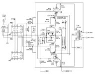
See attached.
Jan
Attachments
Jan ,maybe this can help your project in some way , there`s Made in Japan Softone M7 hybrid PP fully balanced amp where output power EL34 tubes are triode strapped and cathode driven,
btw , I heard some very positive reports about sonics of this amp ,http://softone.a.la9.jp/english/Model7/M7-eng-3.htm
http://softone.a.la9.jp/english/Model7/M7-eng-1.htm
btw , I heard some very positive reports about sonics of this amp ,http://softone.a.la9.jp/english/Model7/M7-eng-3.htm
http://softone.a.la9.jp/english/Model7/M7-eng-1.htm
Attachments
G2 cannot be connected to A in a HV amp.
Therefore a split current is present in any case. Maybe if G2 can be kept negative it is possible but this will cause the tube to starve. I have not tried this, maybe Tubelab has done some experiments in this regard.
Therefore a split current is present in any case. Maybe if G2 can be kept negative it is possible but this will cause the tube to starve. I have not tried this, maybe Tubelab has done some experiments in this regard.
JanI do worry about any current that causes a difference between Ia and Ik and I believe C2 current does cause that.
In my concept it causes distortion, I want Ia to be exactly Ik as far as feasible.
See attached.
Jan
as long as the audio signal drive of the cathode goes only in the positive sving direction, Ia will be equal to Ik, this is valid for example the case when both grids of the GMI-11 tube are directly grounded, with such connected grids, that lamp is a real Triode,
but only in the case when the audio signal drive of the cathode goes in the negative sving direction in relation to the both grounded grids, then the grids current will also start to flow so that Ia will no longer be equal to Ik, in that case Ik will be the sum of Ia+Ig1+ig2.
Last edited:
The combined currents from each and everey electrode of any tube make up the cathode current.
If there is no positive voltage between any grid and the cathode then there is no current.
But, each and every grid and its Ugk influences current flow to the anode to a various degree,
all depends on tube buildup, grid alignements, a.s.o.
If you connect the grids together and drive them actively you get usually a highish mu triode.
Often so high that anode current is almost cut off at Ugk0 and
need pos. gridvoltage, wich means grid current, to get any decent anode current.
But in your case, with kilovolts on the anode, i thinck that the combined 519 mu
will be too low, and you need gobs of voltage to drive that thing.
Some decades ago i dissected a Philps 509 and, if if remember correctly, the grids where very
crude and sparsly wound.
I would just hook up one and try to find out more by practical means.
I never tried running a good sized tube with zero or negative voltage on the screen. Most pentodes, especially big ones, will need some positive voltage on one of the grids to get some current flow. The current drawn by G2 will be very low if the plate voltage remains considerably higher than the screen voltage. You aren't looking for a lot of plate current, so maybe a few volts on G2 will be sufficient? Will your circuit work if the G2 current is supplied by an independent floating supply between the cathode and G2? If so, then that's not too hard to do.G2 cannot be connected to A in a HV amp.
Therefore a split current is present in any case. Maybe if G2 can be kept negative it is possible but this will cause the tube to starve. I have not tried this, maybe Tubelab has done some experiments in this regard.
Which rules out pentodes, or demands a lot of jumping through hoops to use natively pentode valves as triodes. I wonder if the requirement could be relaxed in your (push-pull) case? Suppose that only the G2 signal (but not the DC) currents needed to be equal in your application. Would that mean that you could tie the two G2s together, and feed them from an arbitrarily large impedance from their own supply, chosen for best operating characteristics, and let any G2 signal currents' differences cancel, because push-pull Class A?I do worry about any current that causes a difference between Ia and Ik and I believe C2 current does cause that.
In my concept it causes distortion, I want Ia to be exactly Ik as far as feasible.
The secondary question of DC currents might be minimized by the current source G2 feed sufficiently to keep anode currents in reasonable balance. Of course you want to keep those anode currents in tight balance for headroom in the plate choke. Would a trim resistor in the semi-con driver portion do that job?
Very interesting project; much thanks, as always,
Chris
Yeah that's a good point. Hadn't thought about that. Hmmm.With just a few mA Ia and kilovolts of voltageswing from anode to all other electrodes, there is little hope to get really equal anode and cathode currents at higher frequencies, thinck also of capacitive currents,strays a.s.o, cathode current will always be higher, no?
Jan
Chris, there will be global feedback from output to input. The drop across the inductive load will be about 30V and I can accept that 'unbalance' relative to purely symmetric output. Compare it to offset in a solid state amp slightly offsetting the output so clipping will be assymmetric. Not an issue in practise.Which rules out pentodes, or demands a lot of jumping through hoops to use natively pentode valves as triodes. I wonder if the requirement could be relaxed in your (push-pull) case? Suppose that only the G2 signal (but not the DC) currents needed to be equal in your application. Would that mean that you could tie the two G2s together, and feed them from an arbitrarily large impedance from their own supply, chosen for best operating characteristics, and let any G2 signal currents' differences cancel, because push-pull Class A?
The secondary question of DC currents might be minimized by the current source G2 feed sufficiently to keep anode currents in reasonable balance. Of course you want to keep those anode currents in tight balance for headroom in the plate choke. Would a trim resistor in the semi-con driver portion do that job?
Very interesting project; much thanks, as always,
Chris
There will be two fully independent opposite-phase amplifiers driving the two stators.
I have for about a year an amplifier in service based on this, works very well. It was published in AudioXpress Dec 23 issue.
In a few weeks we'll put up a link to it so also non-subscribers can download. That project was based on the 6HS5, a beam triode.
The new project became necessary because the output is loud enough for listening at elevated level but not drive the ESL 63 to max output.
So basically I am looking for a replacement for the 6HS5 that can handle more Va and more Pa. Target is 8kV and 80W, but 2 // tubes @ 40W is also acceptable. What I found so far is that beam or compactron triodes max out at 5.5kV Va(max). (Beam) pentodes are available with Va(max) of 8kV+ and Pa of 40W+, but that introduces all those grids that complicate things. The other alternatives are RF xmitter tubes like the CV-1256 which is a triode that handles 10kV at 100W.
Jan
As usual, I was unclear. I'd meant DC imbalance in the standing mag field of the anode inductor's core, in the same sense as a conventional amplifier's DC imbalance through its OPT primary, and the same issues. In that respect, that anode inductor needs to be very much like the primary of an OPT. You might even use the 63's step-up's secondary windings with (originally) primaries disconnected, and reserved for emergencies or comparisons.
Re pentode G2 supplies in push-pull: in modern semi-con circuits like this (cascoded push-pull Class A, like input diff-amps) the analogous common G2 connection (the "top" BJT pair's common base terminal) is bypassed, cap coupled or even something fancier, to the junction of CCS and "bottom" emitters or sources.
In really ancient, pre-War, and somewhat post-War push-pull pentode circuits the common G2 connection to power supply was often just through a big resistor, no bypassing. Looks like it would be somewhat self-balancing.
All good fortune,
Chris
So you're making a push-pull amplifier from two single-ended amplifiers? I somehow knew you were up to something about this inductor, and saving it for publication. The nose knows.
So, OK, I give up. I'd sworn off magazines after Linear Audio ended, but if you're gonna play hard ball, I guess I'll have to sign on - it's too interesting to miss.
All good fortune,
Chris
So, OK, I give up. I'd sworn off magazines after Linear Audio ended, but if you're gonna play hard ball, I guess I'll have to sign on - it's too interesting to miss.
All good fortune,
Chris
- Home
- Amplifiers
- Tubes / Valves
- Looking for high-voltage tubes