Music is always on all day over here but I find myself enjoying it much more than before with these amps.Seems like a good amplifier for audiophiles to own for diversity and AB comparisons
I have no idea how my musical experience could be further improved with my current setup.
They are definitely in the top 5 of best amps I ever heard. Highly recommended.
Hugo
Dear Susan,
I appreciate your work. Great idea and great execution.
I read the entire thread.
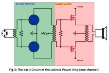
Have you seen the LaSCALA power amplifier?
(https://www.canever.engineering/shop/la-scala-power-amplifier/)
Is it possible that your basic idea was taken from your work?
I appreciate your work. Great idea and great execution.
I read the entire thread.
Have you seen the LaSCALA power amplifier?
(https://www.canever.engineering/shop/la-scala-power-amplifier/)
Is it possible that your basic idea was taken from your work?
Attachments
Wow, that's dedicated - thanksI appreciate your work. Great idea and great execution.
I read the entire thread.
")
Thanks. No, hadn't seen that.Have you seen the LaSCALA power amplifier?
(https://www.canever.engineering/shop/la-scala-power-amplifier/)
Is it possible that your basic idea was taken from your work?
Even if they were aware of my work, my experience in the past is that it would be dismissed as having had no worthwhile contribution or merit to their own designs.
It also shows what one can do with proper funding, as it take a substantial amount to set up and run an audio business making product. I have never had any funding - and found out the hard way that one needs such a thing - hence I have never been in a position to make my ideas into a "real" business.
https://www.monoandstereo.com/?p=8569
They quote 70kHz bandwidth, whereas my system runs at over 200kHz.
I also don't think much of their distortion figures around the 1W mark, looks like c. 0.035% just for the power-amp.
My full line-level input pre-amp/line-driver and power-stage does 0.0054% THD at 1.1 watts (2.89 volts into 8 ohms) - 1 kHz FFT
But who am I to nitpick, I don't have any sales whereas they are selling kit so relative performances are irrelevant.
You made me and many others very happy with your generous gift.But who am I to nitpick,
Hugo
https://www.diyaudio.com/community/threads/zero-feedback-impedance-amplifiers.42259/post-7517999
The input preamp / buffer did suffer from poor PSRR. I build a small cap multiplier as seen here in figure 2.1:
https://sound-au.com/articles/cap-multiplier.htm
Some measurements:
Buffer amplifier alone:

Amplifier with 8 Ohm load:

Distortion:

Noise floor:

Hugo
The input preamp / buffer did suffer from poor PSRR. I build a small cap multiplier as seen here in figure 2.1:
https://sound-au.com/articles/cap-multiplier.htm
Some measurements:
Buffer amplifier alone:
Amplifier with 8 Ohm load:
Distortion:
Noise floor:
Hugo

Sinclair PZ5,6,8 regulated power supplies had a very useful fold-back protection feature. That's a long time ago but well suited for this application.
http://diy.torrens.org/Sinclair/P80/index.html
http://diy.torrens.org/Sinclair/P80/index.html
Same here.I am able to get ripple down to 1mV rms
With +/- 1.5A total load (*) I get 0.16mV rms on one speaker terminal and 0.08mV rms on the other.
* 1.4A for the 34V unregulated rails of the power mosfets and 0.12A on the 15.5V rail for the buffer amp and bias circuit with cap muliplier.
Before I added the multiplier I measured +/- 280mV rms.
Hugo
What distortion orders are the colors of the distortion plot in post #1886? There is an orange line that starts seprating from the dark gray line at about 1.8 kHz. I suppose the gray is THD and the orange HD2? If correct, THD is a lot more than 0.005% at 1 kHz unless this is for a much higher output power than 1.1 W.
The black line is THD, the red is HD2, the orange HD3 and the yellow HD4.
THD at 1kHz is about 0.03% in that graph, I believe.
Please bear with me, I'm only just learning REW and frankly, I think some of these measurements are a bit too optimistic, so thanks for the feedback. One thing I can't figure out is the weird phase response although a scope in XY mode shows a near perfect line. Once I get more grip on the system I'll post more detailed results.
If I were to find another supplier of custom transformers.
What would the preferred transformer specifications look like? What is listed on http://www.audiophonics.com is still valid?
What would the preferred transformer specifications look like? What is listed on http://www.audiophonics.com is still valid?
Apologies, I need to very much get round to updating the website.What is listed on http://www.audiophonics.com is still valid?
You should be able to hand wind the EI-120 transformers yourself.
The input and step-up transformers are a bit more complex to wind (because of the many more turns of fine wire).
What specific information are you looking for?
No worries, just you sharing this project is above and beyond stellar :*
I'm looking to sourcing all the transformers from the East, I do not have the money for Sovters and I am not to keen on trying it myself.
I'm looking at the pages that specify the transformers. I just wanted to know if they were still correct or if some details should be added if I ask to have them produced.
I need 4 channels, so the price becomes an issue.
- Home
- Amplifiers
- Solid State
- Zero Feedback Impedance Amplifiers