Hi: will you please share the schematic of your implementation?grunding solution
easy and simple
great overall sound improvement
thanks 🙂
happy new year 2022
Usualy I use the one attached.
Thank you and happy new tear!
Attachments

Hello! I already done Grundig DEM modding and i like it.
Use my Dac also on NOS mode trought a jlsound i2s over USB card.
I use also Raspberry + Qobuz for streamer my music , but hi res files don't plays on tda1541.
Could I use something (for example an upsampler) or something simpler and above all that doesn't degrade the sound quality ,on the i2s line that goes from the jlsound output to the tda1541 input that allows me to listen to hi res files too?
What do you mean by high resolution data?but hi res files don't plays on tda1541.
.. degrade the sound quality
You call HiRes, that doesn't have higher resolution.
1. on paper it has a higher dynamic range due to the higher bit count. But that has no relation to a better dynamic range for music, nor to what your ears can tolerate without damage.
2. the higher sampling rate only means that you have an extended frequency range in the signal - which is neither in the recording, which your system cannot reproduce and which you cannot hear. Moreover, you then have to add dither again, unless you like weird beeping in your ears.
Do not want to spoil your tinkering mood, but I puzzle how you come up with such an idea.
The TDA1541A happily plays PCM/synchronous 192 which was considered HiRes until recently. Personally I prefer to play 44.1 without oversampling. 44.1 vs 176.4 sound slightly different. It will be a matter of personal taste which one you prefer.
I have used the Grundig DEM circuit which I far prefer to the Phillips reference. I settled on the 100hz DEM with 100u decoupling proposed by ecdesign. This DEM with a very good clock and supercaps on the +-5v will take you to musical nirvana.
But if your taste is for DSD then this is not your chip.
How could it?TDA1541A happily plays PCM/synchronous 192 which was considered HiRes until recently ... supercaps ... nirvana
TDA1541 is a 16 bit, HiRes refers to a higher bit (higher amplitude), commonly used so far 24 bit - apart from that this is just theoretical nonsense. HiRes Wiki
The asynchronous USB input gives it 16 bit to the converter, otherwise you would hear strange stuttering.
Times realized that it is not a higher resolution, only a theoretical but ineffective frequency extension (frequency range <= sampling frequency / 2 ( Nyquist-Shannon). So also at Wiki already the headline is misleading. According to this, already the TDA1541 would be a Hi Res reproduction device, if we put in the oversampling 176.4 again? Not bad to generate a higher resolution from the same microphone recording. Magic.
Damn, so the complete marketing for 24/192 was ********? That's what happens when you only read the first sentence.
Cosa intendi per dati ad alta risoluzione?
Chiami HiRes, che non ha una risoluzione più alta.
1. sulla carta ha una gamma dinamica più elevata a causa del numero di bit più elevato. Ma ciò non ha alcuna relazione con una migliore gamma dinamica per la musica, né con ciò che le tue orecchie possono tollerare senza danni.
2. la frequenza di campionamento più alta significa solo che hai una gamma di frequenze estesa nel segnale - che non è né nella registrazione, che il tuo sistema non può riprodurre e che non puoi sentire. Inoltre, devi aggiungere nuovamente il dithering, a meno che non ti piaccia uno strano segnale acustico nelle orecchie.
Non voglio rovinare il tuo umore armonico, ma mi chiedo come ti sia venuta in mente un'idea del genere.
Hi guys, I just meant that if I set Qobuz 24bit/192khz I only hear a loud noise that doesn't allow me to listen to music.What do you mean by high resolution data?
You call HiRes, that doesn't have higher resolution.
1. on paper it has a higher dynamic range due to the higher bit count. But that has no relation to a better dynamic range for music, nor to what your ears can tolerate without damage.
2. the higher sampling rate only means that you have an extended frequency range in the signal - which is neither in the recording, which your system cannot reproduce and which you cannot hear. Moreover, you then have to add dither again, unless you like weird beeping in your ears.
Do not want to spoil your tinkering mood, but I puzzle how you come up with such an idea.
Setting instead on 24bit / 96khz I solved.
Given that my dac works in non-oversanpling mode.
HI Guys!
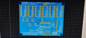
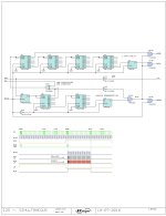
after having spent some time studying the possible solutions, and reading here and there in the different threads, I think I have found the solution to my problem.
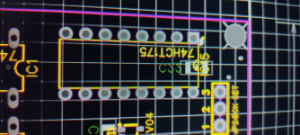
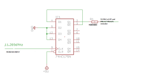
Nothing of mine (be clear...because I'm not capable of it) except the addition of 74hc175 as divisor of Bck (optionable via JP2).
I also added JP1 as well
for use up to 352.8kHz with 11.2896MHz at 32FS.
I would like to have your opinion.
Thanks to ECdesigns for the wiring diagram of its intellectual property.
after having spent some time studying the possible solutions, and reading here and there in the different threads, I think I have found the solution to my problem.
Nothing of mine (be clear...because I'm not capable of it) except the addition of 74hc175 as divisor of Bck (optionable via JP2).
I also added JP1 as well
for use up to 352.8kHz with 11.2896MHz at 32FS.
I would like to have your opinion.
Thanks to ECdesigns for the wiring diagram of its intellectual property.
Attachments
-
 IMG_20230407_184127.png369.5 KB · Views: 146
 -
 IMG_20230407_184115.png448.8 KB · Views: 101
 -
 IMG_20230407_183801.png434.7 KB · Views: 101
 -
 IMG_20230407_183743.png442.9 KB · Views: 90
 -
 IMG_20230407_183724.png422.3 KB · Views: 93
 -
 IMG_20230407_183658.png417.5 KB · Views: 92
 -
 IMG_20230407_183354.png429.5 KB · Views: 147
 -
 I2S to PCM converter.jpeg149 KB · Views: 181
 -
 BCK_RECLOCK.png7.3 KB · Views: 179
Last edited:
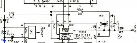
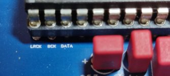
For use you will need to change your DAC mode from I2S to simultaneous (pin 27 (OB/TWC) connect to -5V) ... dac pin 1: LE, pin 2: CL, pin 3: DL, pin 4: DR
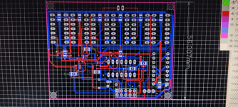
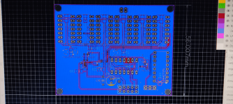
Unfortunately having prepared HEADER 4 did not save me from the modifications I will have to make to the MAIN pcb to pass from i2s (3 wires + gnd) to PCM (4 wires + gnd).
So now he will have to cut and sew some traces under or over there....
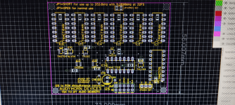
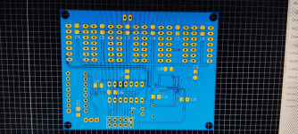
For the Community both the Gerber files and the JSON file.
I hope to do what you like.
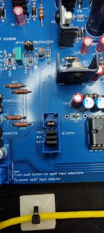
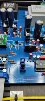
You will notice that the I2S in/out connector is designed for a 10-pin HEADER vertical installation type plug and play referred to my DAC.
Obviously I had already foreseen +5v and GND on the HEADER pins.
Any advice is welcome.
Antonio
Unfortunately having prepared HEADER 4 did not save me from the modifications I will have to make to the MAIN pcb to pass from i2s (3 wires + gnd) to PCM (4 wires + gnd).
So now he will have to cut and sew some traces under or over there....
For the Community both the Gerber files and the JSON file.
I hope to do what you like.
You will notice that the I2S in/out connector is designed for a 10-pin HEADER vertical installation type plug and play referred to my DAC.
Obviously I had already foreseen +5v and GND on the HEADER pins.
Any advice is welcome.
Antonio
Attachments
-
PCB_I2S to PCM Converter Board V2.0 with GROUND PLANE_2023-04-07.zip141.4 KB · Views: 95
-
Gerber_I2S to PCM Converter Board V2.0 with GROUND PLANE.zip138.6 KB · Views: 60
-
 IMG_20230324_215235.jpg327.9 KB · Views: 117
 -
 IMG_20230324_215247.jpg341 KB · Views: 118
 -
 IMG_20230324_215417.jpg360.5 KB · Views: 118
 -
 IMG_20230324_215338.jpg220.5 KB · Views: 118
Last edited:
I implemented the Grundig DEM clock (along with 100uF electrolytic + 100nF ceramic filtering) and it sounds indeed good, even in NOS mode.Hi,
In NOS yes as I am using NOS not 4x oversampling.
Antonio, I don't recommend using tantalum capacitors on the upmost two bits as seen on your photo. They are leaky, unreliable, sensitive to vibration, just to name a few of their issues. Just tap them with the handle of a screwdriver while playing, you will hear it yourself. You'd better use a conventional audio-grade electrolytic capacitor.Any advice is welcome.
Antonio
- Home
- Source & Line
- Digital Line Level
- TDA1541 DEM reclocking