This thread popped up and I started it June 2nd 2009. Must be one of the more longer running threads then ")
When reading some old posts I even see posts by members who have meanwhile passed away. To those who built either Hypnotize or Mezmerize, I salute you!
When reading some old posts I even see posts by members who have meanwhile passed away. To those who built either Hypnotize or Mezmerize, I salute you!
Last edited:
having lighting issue to read colors... just a minute
That particular resistor you can measure correctly without lifting one of its legs when power is off.
all resistors are correct.
I'm hoping replacing the two eBay transistors solves it, might even replace the 7812 while I'm at it.
Hope it isn't the cap, because up until now everything else could probably be done without pulling the board out of the chassis! Would a bad cap cause me to have the 5.15V reading across the input diode?
Thanks to all!
I'm getting 12V across the input relay, 5.15 across the output. I can't see a couple of the cheap resistors under the LM7812. That's the only thing reasonable?
That's good news because the 7812 isn't pulled down and the problem seems local to the output relay's circuit. If local parts are missing or having wrong values or faked its very reasonable to have a problem there.
Would a bad cap cause me to have the 5.15V reading across the input diode?
Thanks to all!
Yes it could upset the circuit so not to work as intended. I have had that reported once. Badly pulled damaged inside reused cap, no relay click.
Non clicking relay is either not enough voltage reaching it due to fault in the control circuit or something's wrong with the relay itself (doubtful).
All parts were new except the IRFP's which are working fine.
The sellers of transistors in question on eBay have 20,000+ reviews with 99.8% positive and 2,000+ with 100% positive. The prices were only marked up for buying an individual transistor, order 10 and the price drops sort of like $5 for one, $6 for ten. They are clearly marked, and question the amount of work to forge a $0.12 part.
That, and I am getting the 12.8V across the diode next to the input relay. 12.8V from cathode side to ground while activated, almost 0V from anode side. The uncharged input relays have 12.8V to ground from both sides of diodes, and nothing measured across the diode.
Now, hopefully a useful measurement:
The output relay diode is measuring 5.15V across it. From the cathode side to ground is 12.09V and from anode side is 6.94V to ground. Adding or subtracting any of these numbers gives the remaining voltage. Does this provide any useful information?
Last edited:
Now, hopefully a useful measurement:
The output relay diode is measuring 5.15V across it. From the cathode side to ground is 12.09V and from anode side is 6.94V to ground. Adding or subtracting any of these numbers gives the remaining voltage. Does this provide any useful information?
Yes, it informs that the LM7812 output is good. It also informs that the relay coil driver transistor isn't conducting. Thus the problem is in the parts of the delay control circuit.
Attachments
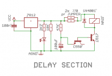
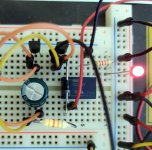
I freshly tested it on a breadboard to give you debugging check voltages. Powered with 12V from a bench supply. I put it to light an Led with its contacts. To can see what it does than just listening for clicks. Relay is the original NAIS TQ2-12V (same as the orange Kemet EA2-12NJ or NU).
With C550 & C517, voltage across diode/coil is 11.27V. C517 collector to ground 0.696V. C517/C550 bases to ground 1.307V. C550 emitter to ground 10.09V. For 47k 100uF RC it takes about 7.5sec to click/light. For 33k 100uF RC it takes 5sec. When starting from a long enough powered off/drained circuit state.
With both transistors C550 it also works (Fairchild CTA). Voltage across diode/coil is 11.80V. C550 relay coil driver collector to ground 0.168V. C550s bases to ground 0.723V. "Predriver" C550 emitter to ground 9.51V (actually applied like a Zener). Seconds to click/light almost the same as before.
*BC550 BC517 pinout is C,B,E 1,2,3 when facing their flat front surfaces.
Attachments
Thanks for the all of the work to provide test points.
I think I mounted the potentiometer backwards... insert stupid emoji here.
New BC550 & BC517 arrive tomorrow.
I'm not sure I want to know what context fake Chinese eggs occurred in - fake egg drop soup or being sole whole? Certainly not fake migas - I could see cardboard substituted for old corn tortilla pieces.
Here is the current variation of it. Private message me, I am doing a group buy for multiple of Salas boards if interested.Hey there! this circuit is exactly what I am looking for. I'd love to buy the PCB from the store but it's sold out - are there any other sources for these pcbs?
GB DCB1 Flexsink Edition
I am building some Hypnotize boards from waaaaay back. I remember some stories back then about PSU asymmetry.
I've seen Salas mention that the asymmetry was in LED bias strings to accomodate PMOS/NMOS differences, and that Hypnotize didn't include it because of expectation of running higher CCS bias.
I'm sure, though, that I remember reading of some benefit to the B1 itself regarding asymmetrical PSU. Does this sound familiar to anyone?
200mA will be a satisfying performance point while sinking directly on a somewhat thick chassis floor without getting too hot. Can also go to 400mA when using moderate size side-sinks. Beyond that it starts dissipating like a small Class A power amp. Asking for analogous sinking and breathing provisions.
Are you having a dual layer blue board or single layer very first issue?
Are you having a dual layer blue board or single layer very first issue?
- Home
- Amplifiers
- Pass Labs
- Building a symmetrical PSU B1 buffer