Is the power supply under load or just on its own? I seem to seem to remember the hmn psu sagging significantly under load. I wonder if that's the case here. Although I would wait for something more definitive before connecting up if the psu isn't connected.Hello,
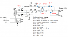
I have a question . I'd like to reduce the voltage output from 415V to 350V . Please tell me what to do.
Thanks,
Output of power supply don't have any load.Is the power supply under load or just on its own? I seem to seem to remember the hmn psu sagging significantly under load. I wonder if that's the case here. Although I would wait for something more definitive before connecting up if the psu isn't connected.
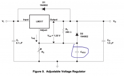
If you are getting 415 out, you have mis-wired the regulator. Take a look at this application note: https://www.ti.com/lit/an/snoa648/snoa648.pdf
Vout = ((56,000/200) + 1)*1.25) + Iadj*56,000.lower the value of R108, from 56k to say 43k....new R108 = 350/(1.25/10) or 43k
Hi anatech Thank you . I measured voltage collector and emitter of Q101 and rectifiers R108 it's too hot.Hi wuttichai,
Okay, what voltages to you have at the rectifiers?, collector and emitter of Q101?
If Q101 didn't regulate the voltage across IC1 to below it's breakdown voltage, it may have shorted instantly. The value of D103 is set to prevent this from happening.
Attachments
Last edited:
Hi TonyTecson , Thank youlower the value of R108, from 56k to say 43k....new R108 = 350/(1.25/10) or 43k
Vout = ((56,000/200) + 1)*1.25) + Iadj*56,000.
Hi jackinnj Thank you
Hi anatech Thank you . I measured voltage collector and emitter of Q101 and rectifiers R108 it's too hot.
yes R108 dissipates around 2.2 watts and gets to be so hot, even 10 watts is good to use there..
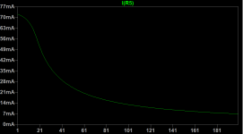
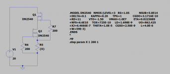
Remove V1, V2. (Q1/Q2, the DN2540 act as current source of a few mA to the 6SN7). Connect the anode end of R4 to ground and measuring the voltage drop, use Ohm's law to calculate the current.Hello everyone
Please help me. Why is the value different?
I have 6sn7+6dj8 set per channel ( 6sn7+6dj8 for right and 6sn7+6dj8 Left). Please tell me how to fix this pro . I have problem voltage different
Perhaps the value of R4 is too low. The parameters of DMosfets can vary quite a bit and it is best to test the current source and adjust the value of R4 to set the current that SY was looking for in his original design.
device differences, a variable pot for R5 ...adjust for same plate voltage, on left and right channels
i think the 6dj8 plate will need to be 1/3 of plate supply, 2/3 's of the rest of the voltage deivided between two resistors...
once the pot adjustments get you the operating ppoint, then you can measure the pot resistance and replace it with a closest standard value fixed resistor...
this is how i would do it...
You're right, the two halves of the triode may be somewhat different.device differences
this is how i would do it...
If you just put a 10K potentiometer in parallel with R5 there is no necessity of removing it...that's how I do it with "His Master's Noise"
Hi jackinnj , Thank you . Hi TonyTecson, Thank you.
Is work for differences plate voltage but. I am unsure one 6sn7 have problem voltage issue of grid is increasing from 0.0002 V is greater than 1 V in status idle. (no input signal and volume lowest) and plate voltage reduce. And if increase volume voltage of plate is reduce . But the other 6sn7 no issue.
Sorry, my English is poor
Hello wuttichai did you first solved the problem with your power supply?
It seems that you have fried your LM317 because 415volt is excessive. The final measurements need the audio circuit to load the power supply.. I would start with this problem first.
One thing I also found out with my implementation was I needed the Cadj as per LM317 datasheet or else the supply had noise.
One more thing is to check before and after the LM317 voltage to ground and you need more than 5volt in order to be safe.
When I made my Impasse the component values for the power supply didn't work well for me and I had to change some of them in order to obtain the stated performance.
When you fix this, I believe you have to check the R5 in order to have both CSS perform as stated (about 8mA ,as Tony and Jack said above) and then you have to bias the 6dj8 by altering the voltage divider after the output of the 6SN7.
The voltages on the right channel at the 6Dj8 doesn't make any sense to me now, I would follow the above steps and measure again.
Attachments
my experience with depletion mosfets is that they also have wide differences between samples, so the thing is to be able to find devices that are closely matched for CCD duties...before soldering them into the boards..
Thank you
- Home
- Amplifiers
- Pass Labs
- ImPasse Preamplifier